ENGLISH
- 49 -
B1 - B2 230Vac courtesy or flashing lights
K1 Motor 2 (+)
K2 Motor 2 (ground)
K3 Motor 2 (-)
K4 - K5 12V electrolock
K6 - K7 24V courtesy or flashing lights
K8 +24Vdc supply - photocell/optical edge TX for
functional Test
K9 Accessory power common (-)
K10 +24Vdc supply for photocells and other
accessories
J1 START - Open command for connecting
traditional devices with N.O. contact
J2 START P. - Pedestrian open command for
connecting traditional devices with N.O. contact
J3 STOP command. N.C. contact
J4 Common (-)
J5 Exterior photocell. N.C. contact
J6 Interior photocell. N.C. contact
J7 Type 1 edges (fixed). N.C. contact
J8 Type 2 edges (mobile). N.C. contact
J9 Accessories common (-)
A1 Antenna shield
A2 Antenna
BATTERY Battery pack (code 161212)
RECEIVER Connector for MR2 receiver
ADI Module interface
M1 Motor 1
24Vdc
Power Supply
Control unit power supply (+24 VDC)
OVERLOAD Signals an overload on the accessory power
supply
PLEASE NOTE: the highlighted connections are
factory pre-wired
5 - CONTROL PANEL
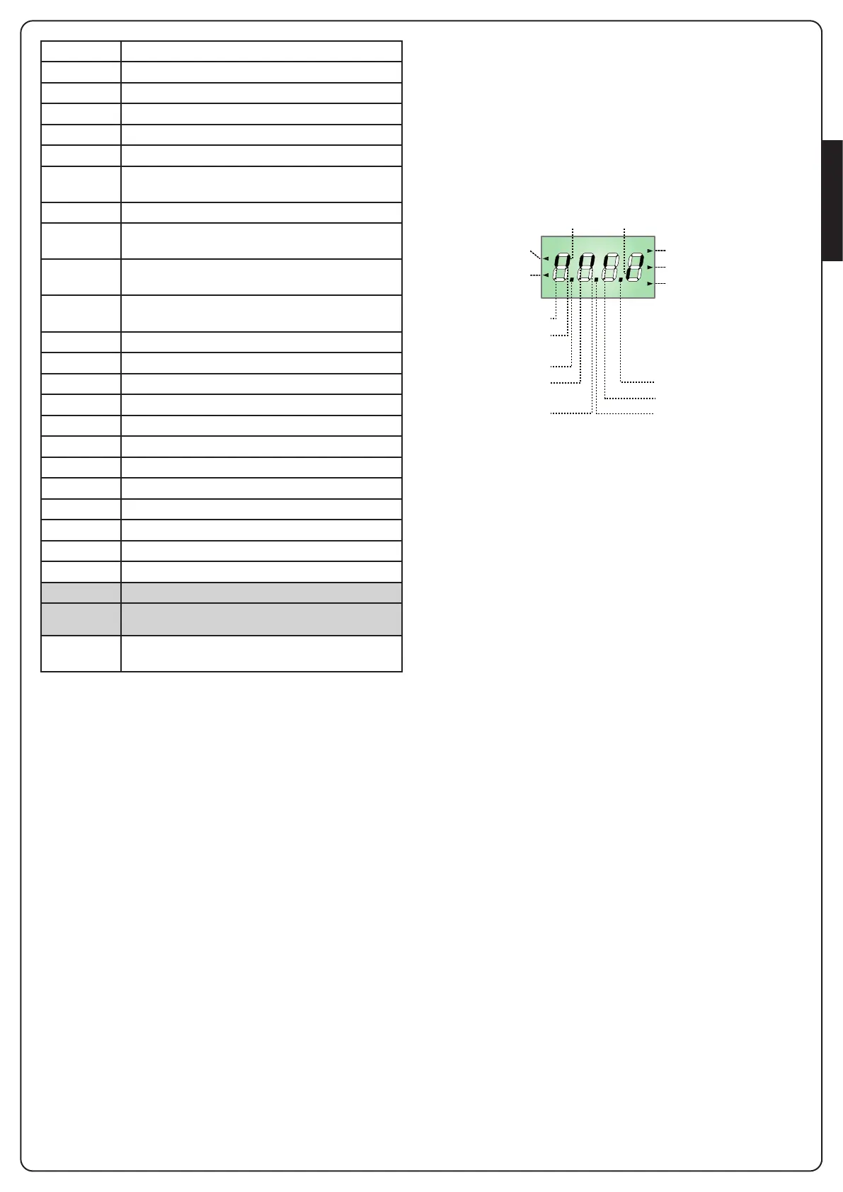
5.1 - DISPLAY
When power is on, the control unit checks that display correctly
operates by switching on all segments for 1.5 sec. 8.8.8.8.
Firmware version, e.g. Pr I.5, will be viewed in the following
1.5 sec.
Panel will be viewed upon completion of this test.
OPENING IN PROGRESS
OPENED CONTACTCLOSED CONTACT
START
PEDESTRIAN
START
PAUSE (GATE OPENED)
CLOSING IN PROGRESS
SAFETY RIBBON 2
OK
STOP
EXTERNAL
PHOTOCELL
INTERNAL
PHOTOCELL
SAFETY RIBBON 1
The control panel represents the physical status of the terminal
board contacts and of the program mode keys: if the upper
vertical segment is on, the contact is closed; if the lower vertical
segment is on, the contact is open (the above picture shows an
instance where the inputs PHOTO, PHOTO-I, EDGE and STOP have
all been correctly connected).
PLEASE NOTE: if the panel is off, the control unit should be
in ENERGY SAVING mode; press the OK key to turn it on.
Points being among display digits show the status of
programming push-buttons: as soon as a push-button is pressed,
its relevant point turns on.
The arrows on the left of the display show the state of the start
inputs. The arrows light when the related input is closed.
The arrows on the display right side show the gate status:
• The highest arrow turns on when the gate is into its opening
phase. If it blinks, it means that the opening has been caused
by a safety device (border or obstacle detector).
• The central arrow shows that the gate is on pause.
If it blinks, it means that the time countdown for the
automatic closing has been activated.
• The lowest arrow blinks when the gate is into its closing
phase. If it blinks, it means that the closing has been caused
by a safety device (border or obstacle detector).