ENGLISH
- 40 -
3.2 - INSTALLATION OF THE REAR FIXING
BRACKET
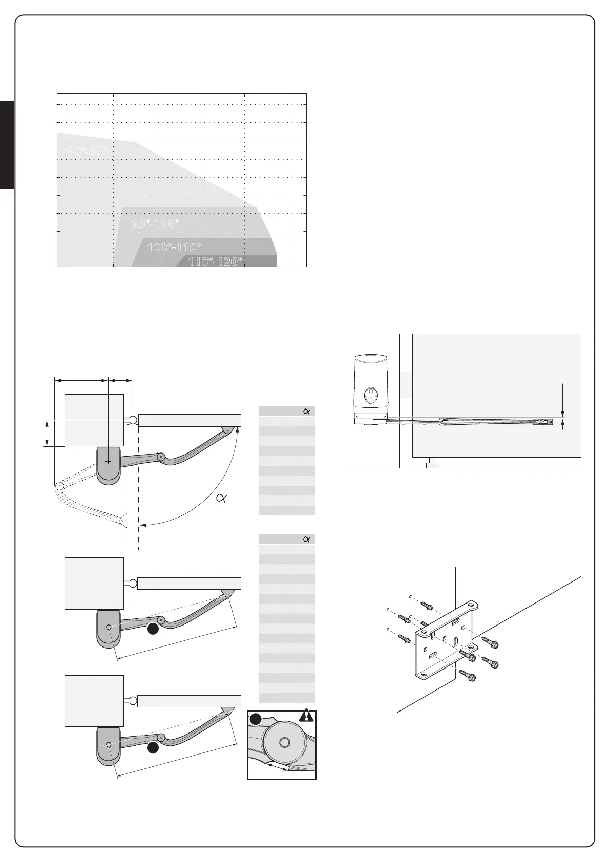
Calculate the rear bracket position using chart.
100
150
200
250
300
350
400
450
100 150 200 250 300 350
C
(mm)
A
(mm)
100°-110°
110°-120°
95°-100°
90°-95°
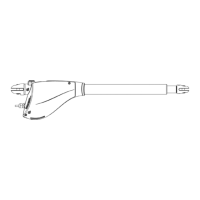
This chart is used to define distances A and C and the leaf
maximum opening angle.
A
max
398
C
162272
162271
max 655 mm
A C
140 30 90
250 30 110
140 80 90
185 80 100
140 130 90
170 130 95
140 160 90
160 160 95
140 200 90
150 200 90
140 240 90
150 240 90
140 280 90
170 280 90
140 320 90
170 320 90
162271
A C
140 30
250 30
140 80
190 80
140 130
170 130
140 160
160 160
140 200
160 200
162272
max 800 mm
90
120
90
100
90
100
90
95
90
95
1
1
1
1. Measure value “C”, then trace a straight horizontal
line in chart 1 against the obtained valued. Select
a point in the line, taking into account the desired
opening angle, suitable for the column.
2. Trace a vertical line starting from the point identified
and obtain value A.
3. Before proceeding with the installation, make sure
that value A allows to fix the rear bracket, otherwise
select another point on the chart.
4. Finally, to fix the bracket on the leaf, refer to the
maximum dimensions of the arm.
Failure to comply with the bracket installation
distances may lead to automation operation faults,
such as:
- Cyclical movements and accelerations at some
positions of the stroke
- Increased motor noise
- Limited opening, or no opening at all (in case of
counter-lever fixed motor)
m WARNING! Before fixing the rear bracket, make
sure that the front bracket will be fixed to a solid
position of the gate leaf; the front bracket will have
to be secured at a different height than the rear
bracket.
5 mm
5. At this point, mark on the leaf and on the wall the
holes of the brackets which will then be used to fix
the two brackets
6. Fix the rear bracket of the motor to the wall
complying with the dimensions seen previously
Installation
examples