ENGLISH
- 51 -
inF
Ch1
AP1
AP2
Ch2
Er93
Er94
Er91
SinG
doP
?
1
2
?
3
4
t.LAu
Ft.no
Ft.S i
ESC
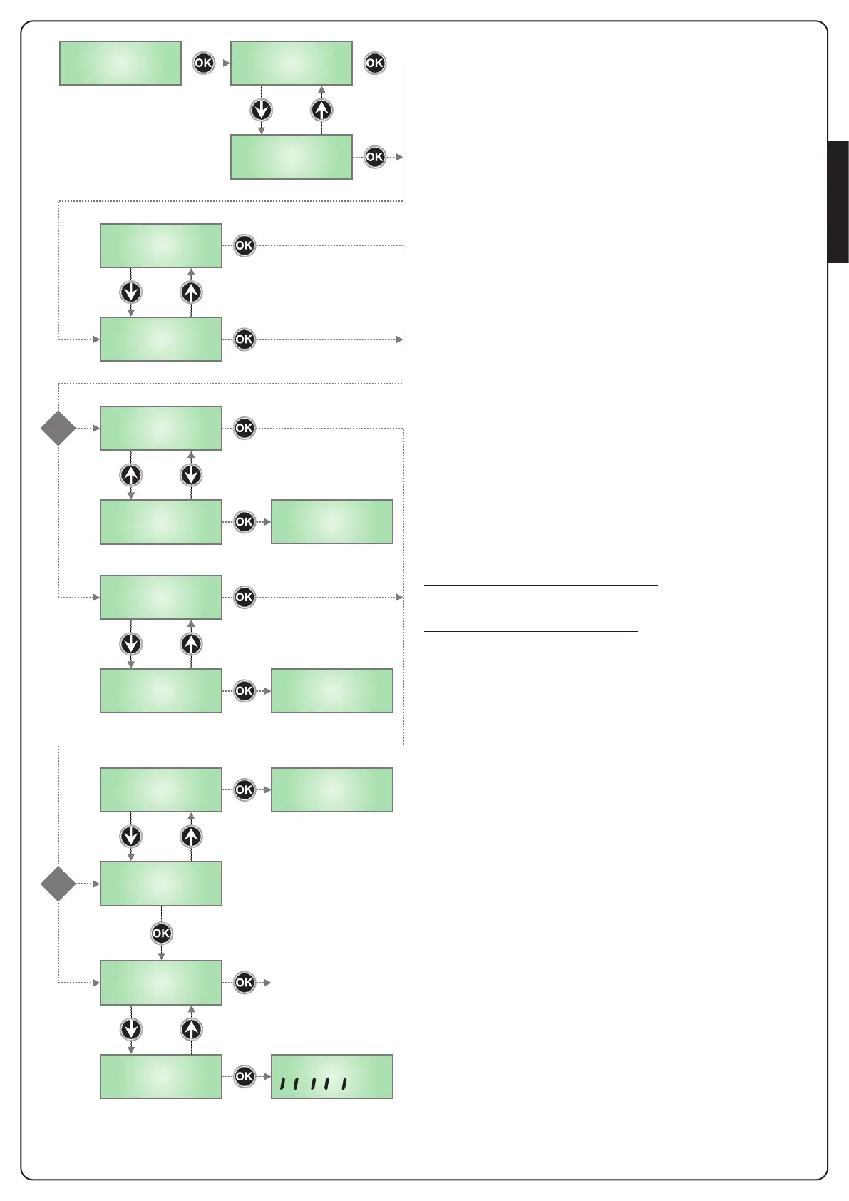
Select this parameter depending on the position (superior or inferior)
of the gate leaf in motion
SUP the gate leaf in motion is the leaf that should open first
inF the gate leaf in motion is the leaf that should open second
PLEASE NOTE: if installation envisages one motor only, select SUP
Select this parameter depending on the direction of opening of gate
leaf 1
AP1 the gate leaf is opening
Ch1 the gate leaf is closing
Having selected this parameter, the control unit moves the
SLAVE motor
1 If the control unit detects the SLAVE motor, the display shows AP2
Select this parameter depending on the direction of opening of gate
leaf 2
AP2 the gate leaf is opening
Ch2 the gate leaf is closing
Having selected the parameter, press OK to move to the next phase.
If the display shows Er93, this means the SLAVE motor is connected
incorrectly.
Check the SLAVE motor connection and repeat the initialisation
procedure
2 If the control unit does NOT detect the SLAVE motor,
the display shows SinG
If the installation envisages only one motor, press OK to move to the
next phase.
If the installation envisages two motors, select the doP menu option
and press OK.
The display will show Er94 to indicate that the SLAVE motor is not
connected, or is connected incorrectly.
Check the SLAVE motor connection and repeat the initialisation
procedure
3 If the control unit does not detect a photocell on the PHOTO input,
the display shows Ft.no
If the installation does not envisage the use of a photocell, select
Ft.no and press OK to move to the next phase.
The photocell will be automatically disabled.
If installation envisages the use of a photocell, select Ft.Si and press
OK. The display will show Er91 to indicate that the photocell is not
connected, or is connected incorrectly.
Check the photocell connection and repeat the procedure.
4 If the control unit detects a photocell connected correctly to the
PHOTO input, it automatically switches to the working time
self-training phase.
Press OK to start the self-training phase.
Select ESC and press OK to exit the menu without performing the
time self-training phase.
Please note: in the case of exiting without self-training, it will
not be possible to operate the gate.
In any case, it will be possible to perform self-training in a separate
phase and program the remainder of the control unit functions, using
the specific menu.