1.4 Setup
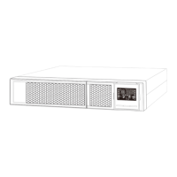
1. UPS input connection
Plug the UPS into a grounded receptacle only. Avoid using extension cords, power strips or surge protectors
2. UPS output connection
There are two kinds of outputs: programmable outlets and general outlets. Please connect non-critical devices to the
programmable outlets and critical devices to the general outlets. You may extend the backup time to critical devices by
setting shorter backup time for non-critical devices
3. Communication connection (Optional)
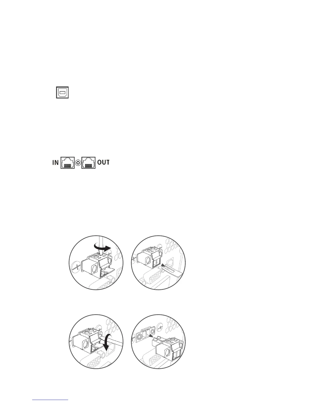
USB Port
4. Network connection
Network/Fax/Phone surge port
Method 1
Remove two top screws Pull out metal pin
Method 2
Remove two front screws Pull out the entire green connector
To allow for unattended UPS shutdown/start-up and status monitoring, connect the included USB cable from the
computer to the UPS system
Note: USB port and RS-232 port can’t work at the same time.
5. Disable and enable EPO function
This UPS is equipped with EPO function. Pin 1 and Pin2 are closed by default for normal UPS operation.
Note: The EPO function logic can be set up via LCD setting. Please refer to program 08 in UPS setting for the details
Connect a single modem/phone/fax/network line into surge-protected “IN” outlet on the back panel of the UPS unit.
Connect from “OUT” outlet to the equipment with another modem/fax/phone/network line cable.