VACON CX Profibus user’s manual Page 23
________________________________________________________________________________________
________________________________________________________________________________________
Vacon Oyj Phone +358-201-2121 Fax: +358-201-212 205
APPENDIX A
CONNECTIONS (small Profibus DP Board, Vacon CX210OPT)
Board layout
Terminals:
X5 Screw terminal to Profibus DP
Diagnostic LED:
H1 Data Exchange state for Profibus DP, Red.
H1 led is active when Fieldbus board is not ready to exchange data
H3 Supply Voltage, Red.
H3 led is active if the Fieldbus board has supply voltage.
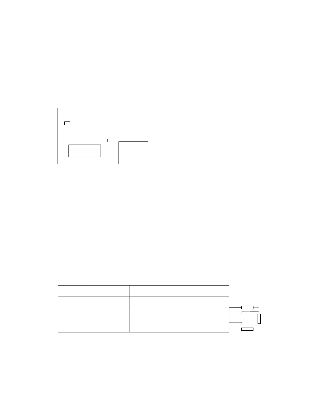
Profibus connections
Screw Connector connector X5: (Terminal resistors not included in the package)
Signal Connector X5
Description
Shield X5-1 Cable shield
VP X5-2 Supply voltage of the terminating resistance
RxD/TxD-P X5-3 Receive/Transmission data positive (B)
RxD/TxD-N X5-4 Receive/Transmission data negative (A)
DGND X5-5 Data Ground
Table 1. D-sub connector
Note! If Vacon is the last device then the bus termination must be set. Install the resistors to the screw
terminal (see table 5-1)
H3
X5
H1
1 2 3 4 5
Figure 1. Profibus board
390 Ω
220 Ω
390 Ω
Termination for
the last node
 Loading...

