VACON CX Profibus user’s manual Page 4
________________________________________________________________________________________
________________________________________________________________________________________
Vacon Oyj Phone +358-201-2121 Fax: +358-201-212 205
2. SPECIFICATIONS
2.1 General
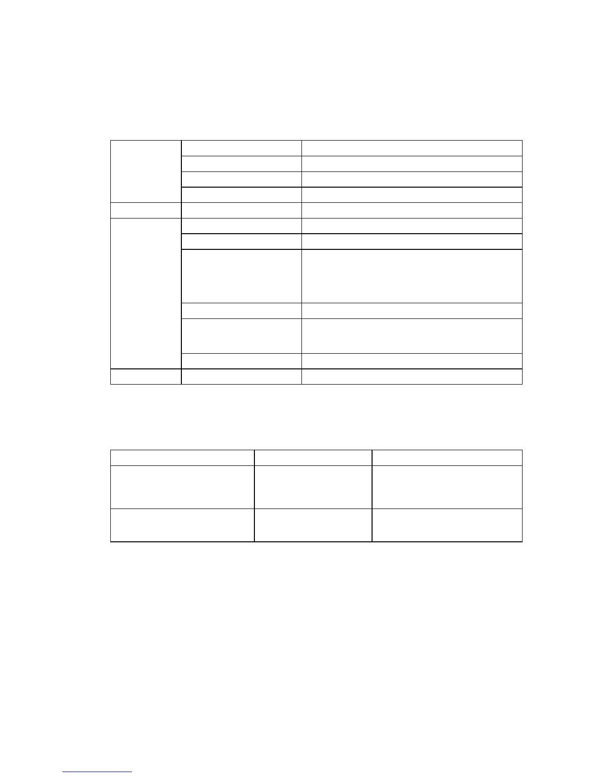
Profibus DP -
Interface 9-pin DSUB connector (female)
connections
Transfer method RS-485, Half duplex
Transfer cable Twisted pair (1 pair and shield)
Electrical isolation 500 V DC
I/O -control
Digital input (4 pcs)
24 V: “0” ≤10 V, “1” ≥18 V, R
i
= 5 kΩ
connections
Digital output (4 pcs) Open collector output, 50 mA/48 V
Relay output (1 pcs) Max.switching voltage: 300 V DC, 250 V AC
Max.switching load: 8 A / 24 V DC
0,4 A / 300 V AV
2 kVA / 250 V DC
Max.continuous load: 2 A rms
Thermistor input (1 pcs)
R
trip
= 4.7 kΩ
Encoder input (3 pcs)
24 V: “0” ≤10 V, “1” ≥18 V, R
i
= 3.3 kΩ
5 V : “0” ≤2 V, “1” ≥3 V, R
i
= 330 Ω
Aux. voltage
24 V (±20%), max 50 mA
Safety
Fulfils EN50178 standard
Communication mode
Profibus DP
PPO types
1
2
3
4
Communication parameters
- Address
- Baud Rate
1 to 127
9.6 kBaud to 12 MBaud
Table 2-1. Profibus communication data
2.2 Profibus cable
Profibus devices are connected in a bus structure. Up to 32 stations (master or slaves) can be
connected in one segment. The bus is terminated by an active bus terminator at the beginning and end
of each segment (see figure 2-1). To ensure error-free operation, both bus terminations must always be
powered. When more than 32 stations are used, repeaters (line amplifiers) must be used to connect the
individual bus segments.
The maximum cable length depends on the transmission speed and cable type (see table 2-4). The
specified cable length can be increased by the use of repeaters. The use of more than 3 repeaters in
series is not recommended.