VACON CX Profibus user’s manual Page 10
________________________________________________________________________________________
________________________________________________________________________________________
Vacon Oyj Phone +358-201-2121 Fax: +358-201-212 205
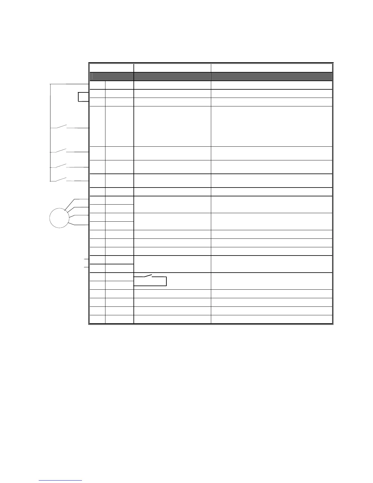
5.3 I/O-control connections
Terminal Signal Description
201…205 Not used
206 +24 V Control voltage output Voltage for switches, etc. max. 0.05 A
207 GND I/O ground Ground for reference and controls
208 COME Common for DIE1-DIE4 Connect to GND or +24 V
209 DIE1 Programmable:
External fault
OR
Selection of active control
source
Contact open = no fault
Contact closed = fault
Contact open = VACON IO-terminal
Contact closed = Fieldbus
210 DIE2 Run disable Contact open = start of motor enabled
Contact closed = start of motor disabled
211 DIE3 Acceler. / Decel. time
selection
Contact open = time 1 selected
Contact closed = time 2 selected
212 DIE4 Jogging speed selection Contact open = no action
Contact closed = jogging speed
213 Not Used
214 DIE6A+
215 DIE6A-
Pulse input A
(differential input)
216 DIE7B+
217 DIE7B-
Pulse input B
(differential input)
90 degrees phase shift compared
to pulse input A
218 DOE1 Encoder direction output
219 DOE2 Encoder divider 1/64 output
220 Not Used
221 TI+
222 TI-
Thermistor input
225 RO4/1
226 RO4/2
Relay output 4, FAULT
231 DOE3 Open collector output 3 READY
232 GND I/O ground Ground for reference and controls
233 DOE4 Open collector output 4 RUN
234 GND I/O ground Ground for reference and controls
Figure 5-2. Control connections
NOTE! Thermistor input (Terminals 221 and 222) must be shorted if not used
READY = ON, when mains voltage has been applied and VACON CX is ready to operate
RUN = ON, when the motor is running
FAULT = ON, if a fault occurs
Enco-
der
Signal from
motor thermistor
 Loading...


