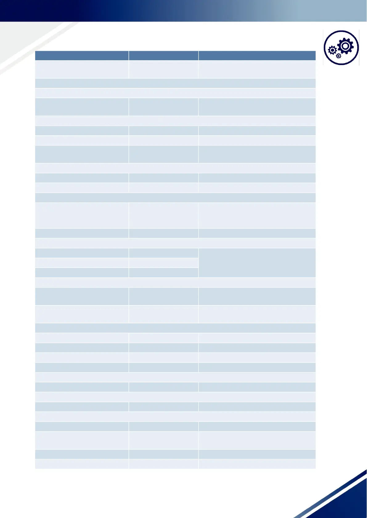
TECHNICAL DATA 21
Operation EN60721-3-3
EN60721-3-7
3M4
7M2
Electrical
Mains connection - X1
TT, TN (with grounded neutral
point)
Operation permitted without restrictions
Motor connection - X2
Number of motor connections 1
Length of the motor line < 5m from motor plug
Line type shielded servo-cable, e.g. LAPP: Ölflex servo,
FD-755-CP
Integrated switching power supply
Output voltage +24VDC
Output current max. 0.5 A incl. all outputs (current limited)
Installation conditions
Installation location depending on the application, the control
system must only be used for the application
for which it was designed
Installation position vertical
Installation clearances
Top The actual installation clearances depend
on the plugs used and the bending radii of
the cables
Bottom
At the side
Drive/frequency converter
Information about the motor con-
nection
Section: “Motor connection”
Information about the frequency
converter
Section: “Frequency converter”
Communication
Communication types HW, PCB and SMGM
Information about HW Section: “HW”
Information about PCB Section: “PCB”
Information about SMGM Section: “SMGM“
Flange/peripheral
Information about the flange Section: “Flange”
Display module
Display type OLED, 2x16 characters
IR interface
Usage Manual mode through infrared interface
Required accessories MC8/10M - Infrared remote control
EHB Tool - Parameterizing software
External data storage
Type DCS DS
Information Basis Description