COMMUNICATION 49
10.2 Rail bus (PCB)
10.2.1 Basics
The rail bus (Power CAN bus) permits the control of complex applications as well the cyclic data transmission
on the entire driving route. A continuous monitoring of the driving parameters, such as speed and position, is
possible, due to the cyclic communication between PLC and mobile control system. In addition, it is possible
to query additional parameters (e.g. temperatures) through an non cyclical data retrieval. In addition, occurring
possible faults can be easier identified through specific error codes and therefore they can be resolved quickly.
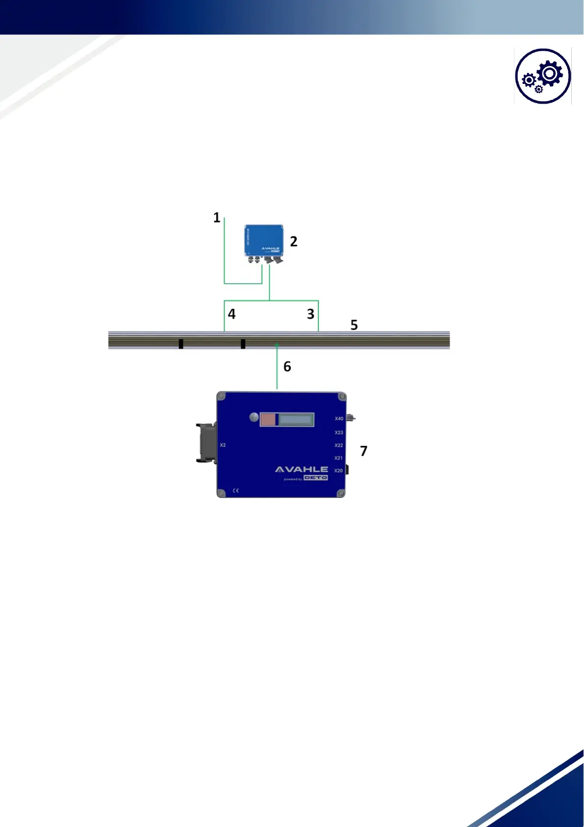
Fig. 10-1 Schematic diagram PCB communication (without additional peripherals)
1: Ethernet wire from/to the stationary PLC
2: Stationary rail bus module (IC-PCB-2K xxx)
3: Wire to the main segment
4: Wire to the separating segment
5: Contact wire in the VAHLE current rail system
6: Wires with mobile communication consumers
7: DCS1 control system (rail bus module integrated)
Additional information about the rail bus can be found in the technical documentation: IC-PCB-2K or contact
the VAHLE technical sales.