DCS1 CONTROL SYSTEMS 25
6.3 Connections and display elements
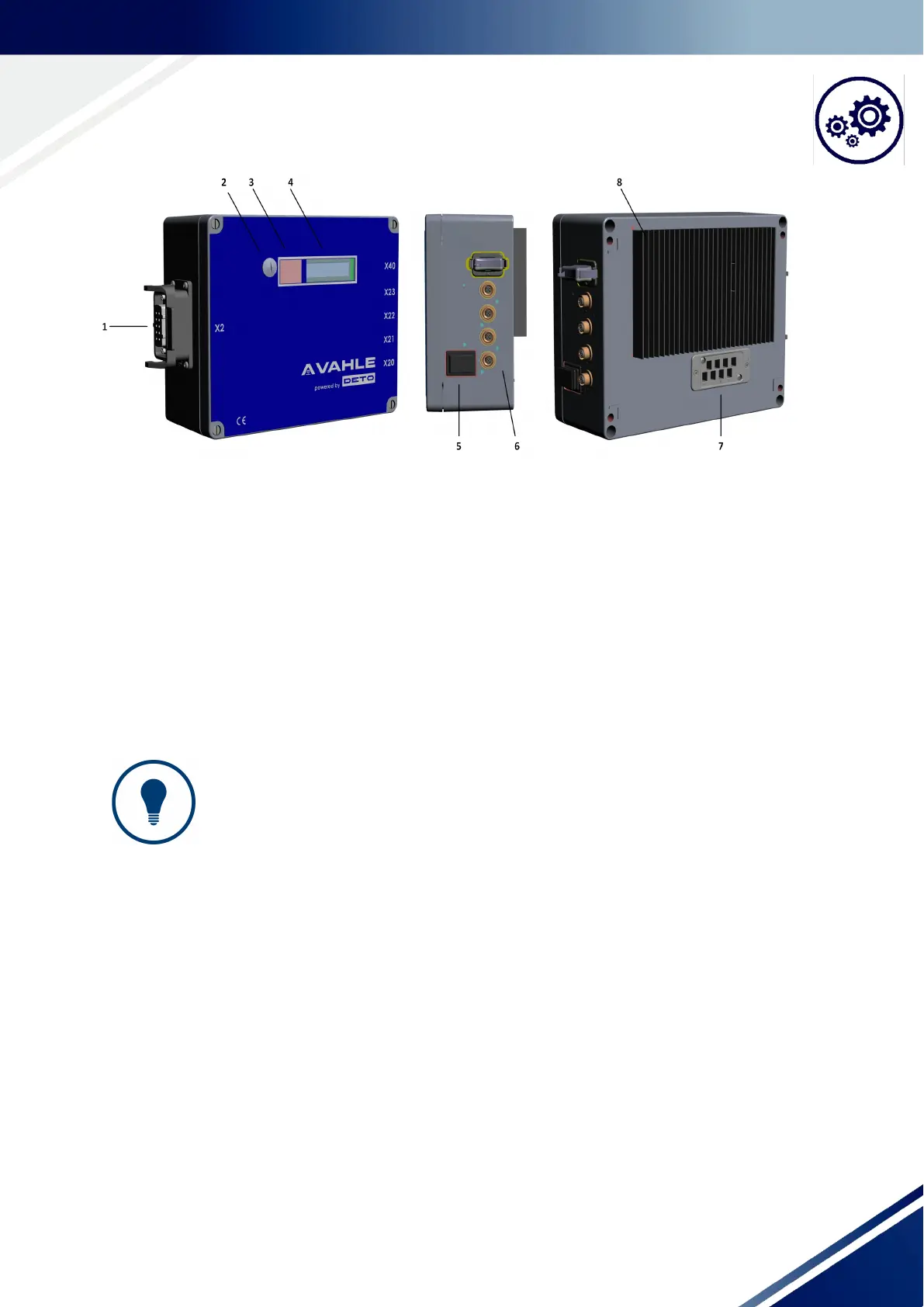
Fig. 6-2 DCS1 control system (standard configuration, with the heat exchanger)
1: Motor connection
2: Cover of the USB configuration interface
3: Infrared interface
4: Display
5: On/off switch
6: Flange (IO)
7: Mains connection – plug field for AC supply (HW and PCB communication connection)
8: Heat exchanger (only for 1.5 kW control variant)
TIPS AND RECOMMENDATIONS!
Information about the connections and displays
► Mains connection: “8.1 Mains connection“
► Motor connection: “8.2 Motor connection“
► Flange: “8.3 Flange“
► Displays: “7 Displays“