LAYOUT AND FUNCTION 52
11 LAYOUT AND FUNCTION
11.1 System overview
External interfaces of a DCS1 control system
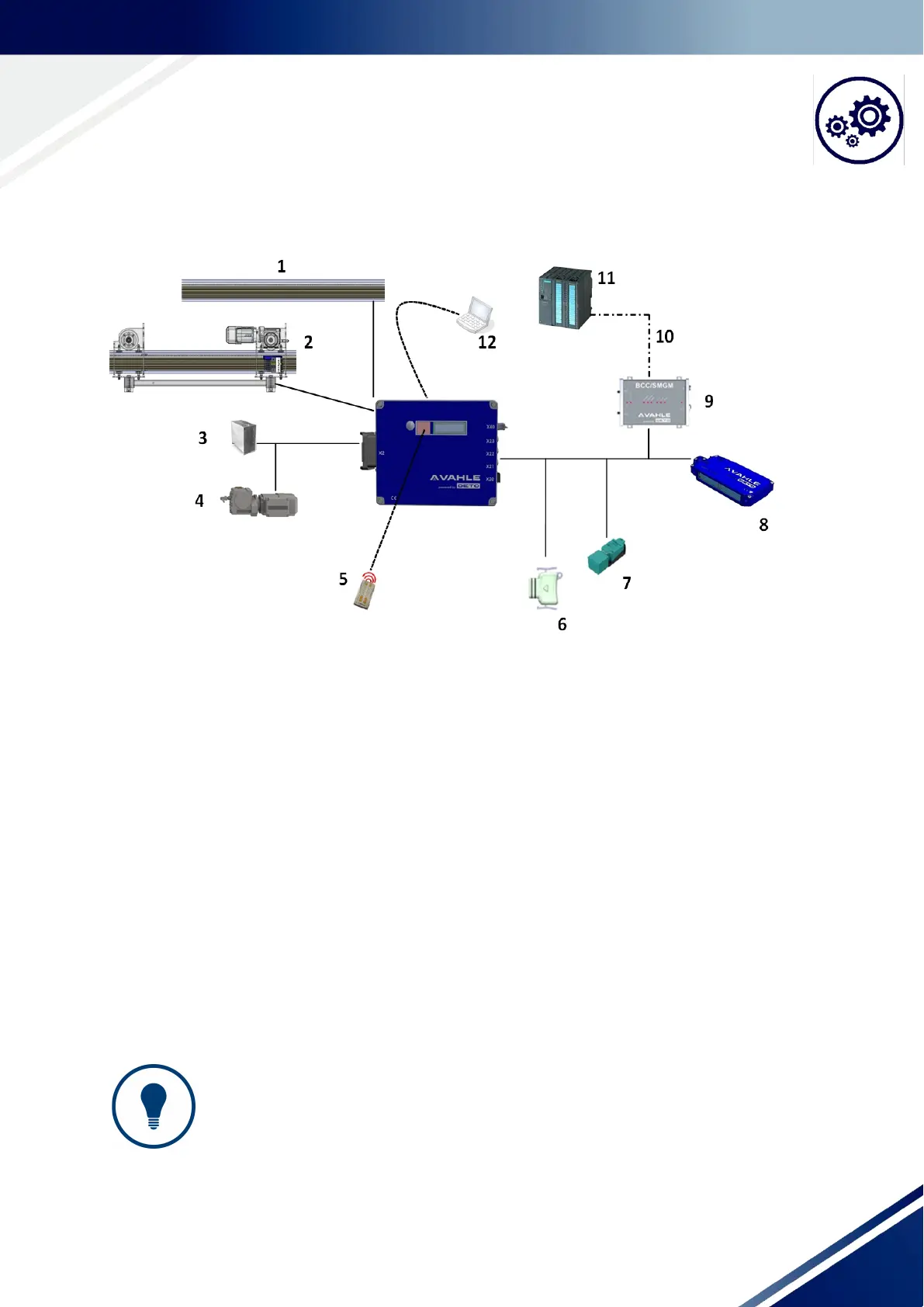
Fig. 11-1 External interfaces of a DCS1 control system (schematic diagram)
1: Supply voltage from the current rail
2: Mobile vehicle/fastening location of the DCS1 control system
3: brake resistance
4: Motor
5: IR remote control: MC8/10M (maintenance/service)
6: Data connector: DS-VD; must be installed
7: Several sensors and actuators
8: Absolute position, e.g. APOS optic; (for half cycle, e.g. EMD4P (absolute position only with external IrDA mod-
ule))
9: Communication module (here: BCC/SMGM); module integrated for other communication types (HW / PCB)
10: Transmission route (here: SMGM rail, rail bus or half cycle also possible)
11: Stationary PLC
12: Laptop/PC with EHB tool (parameterizing of the control system)
TIPS AND RECOMMENDATIONS!
Information about the interfaces
The number and type of the peripherals assemblies depends on the configuration of
the DCS1 control and the system. The figure shows an example for external interfaces
in a DCS1 control system.