DISPLAYS 28
A transfer to the status display occurs after pressing the button [SCROLL].
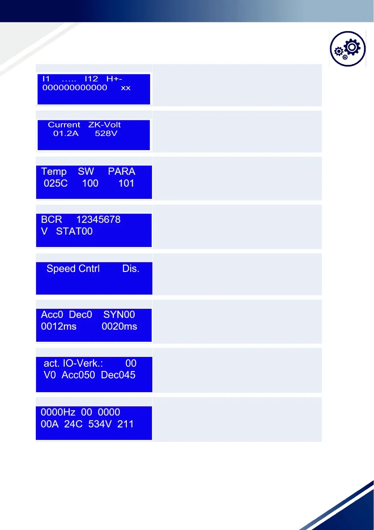
Display Explanation
Only for HW communication type! The state of the individual in-
puts is displayed here. H12 represents the half cycle signal 1
and 2. + represents the positive, - represents the negative and
x represents the full cycle. 0 means no signal.
Display Explanation
Current motor current and current intermediate circuit voltage.
Display Explanation
Temperature of the output stage, software version and parame-
ter version.
Display Explanation
Current sent value from the bar code reader and the status byte.
Display Explanation
Status of the speed controller
Display Explanation
Only communication type HW and PCB!
Current acceleration and deceleration ramp, SYNC message
(HEX). Current timeout time, maximum timeout time (parame-
ter).
Display Explanation
Only HW communication type!
Current active IO link and the resulting speed, acceleration
ramp [Hz/s] and deceleration ramp.
Display Explanation
Current frequency, status byte FUP CPU, error WORD FUP CPU,
current motor current, output stage temperature, intermediate
circuit voltage and FUP CPU firmware version.