Installation
ecoTEC plus installation and maintenance instructions 0020134823_01 15
4
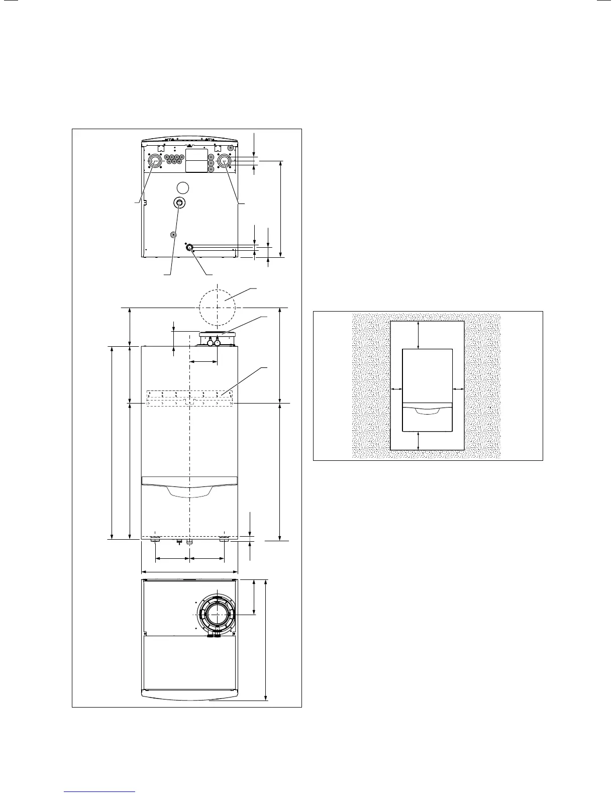
4.3 Dimension drawing and connection
dimensions
287
190
673
603
480
175
138
172 172
70
22
482
Ø25
49
G 1 1/4
960
477
680,5
1
2
3
4
5
6
7
4.1 Connection dimensions in mm
Key
1 Wall breakthrough for flue pipe
2 Flue pipe connection
3 Hanging bracket
4 Heating flow
5 Condensate siphon connection
6 Gas connection
7 Heating return
4.4 Requirements for the installation site
4.4.1 Required minimum clearances/installation
clearances
CC
AB
4.2 Recommended minimum clearances/installation clearances
Key
A 350 mm (flue pipe diameter 110/160 mm)
450 mm (with cascade design)
B 400 mm
C optional approx. 200 mm
> When using the accessories, observe the minimum clear-
ances/installation clearances.
> Where units are installed in cascade, observe the gradi-
ent of the flue pipe (approx. 50mm/m).
i
When installing the 110/160 mm flue pipe,
observe the minimum clearances in accordance
with ¬fig. 4.1.
A side gap is not required, however you can remove the
side panels if there is sufficient space at the side
(approx.200 mm) for maintenance.
It is not necessary to ensure sufficient clearance between
the boiler and combustible materials or components as the
temperature of the boiler will always be less than the maxi-
mum permissible temperature of 85 °C due to its nominal
heat output.