Electrical installation
26 ecoTEC plus installation and maintenance instructions 0020134823_01
8
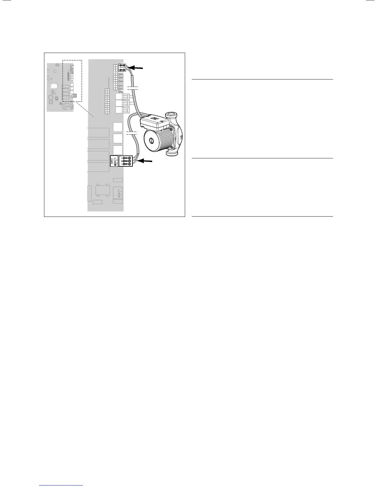
X18
230 V
X22
8.3 Connecting the pump group to the PCB
> Guide the pump cable for the pump group through the
cable duct to the right on the underside of the unit.
> Uses the strain reliefs provided.
> Connect the power supply network plug of the pump
group to the X18 slot on the PCB (¬fig.8.3).
> Connect the control cable of the pump group to the X22
slot on the PCB (¬fig.8.3).
> Lay the lines correctly.
> Secure the lines using the strain reliefs in the electronics
box.
> Close the electronics box (¬section8.2).
i
Ensure that the connection cables are securely
fastened to the plug terminals.
8.4 Connecting the controller
8.4.1 Fitting the controller
> Fit the controller in accordance with the respective
installation instructions.
8.4.2 Connecting controllers to the electronic
system
b
Caution.
Risk of damage caused by incorrect
installation.
Connecting wires that have been stripped
too far may cause short circuits and dam-
age the electronics if a strand accidentally
comes loose.
> Only strip the lines a maximum of 3 cm
to prevent short circuits.
> Lay the lines correctly.
> Use strain reliefs.
b
Caution.
Risk of material damage caused by incor-
rect installation.
Mains voltage at the incorrect plug termi-
nals on the ProE system may destroy the
electronics.
> Do not connect a mains voltage to the
eBUS terminals (+/-).
i
Make sure that the conductors are securely fas-
tened to the plug terminals of the ProE plug.
> Open the electronics box (¬section8.2).
> Guide the supply lines of the components to be con-
nected (e.g. external controller, external sensor) through
the cable duct to the left on the underside of the unit.
> Insert the supply lines into the electronics box.
> Uses the strain reliefs provided.
> Shorten the supply lines as necessary.
> Strip the supply lines 2 - 3 cm, but not more than 3 cm.
> Strip the conductor on the supply lines.
> Fit conductor end sleeves on the stripped ends of the
conductors.
> Connect the ProE plug to the supply lines of the control-
ler using a screwdriver.
> Insert the ProE plug into the associated PCB slot
(¬fig.8.4).
> Lay the lines correctly.
> Secure the cable in the electronics box using the strain
reliefs.
> If you do not connect a room/timer thermostat to the
boiler, bridge the input RT 24 V if no bridge exists.
> If you connect a room/timer thermostat to the boiler,
remove the bridge at input RT 24 V, if a bridge exists.
> If you connect a weather-controlled compensator or
room temperature control system via eBUS, then bridge
input RT 24 V, if no bridge exists.
> Close the electronics box (¬section8.2).