Electrical installation
28 ecoTEC plus installation and maintenance instructions 0020134823_01
8
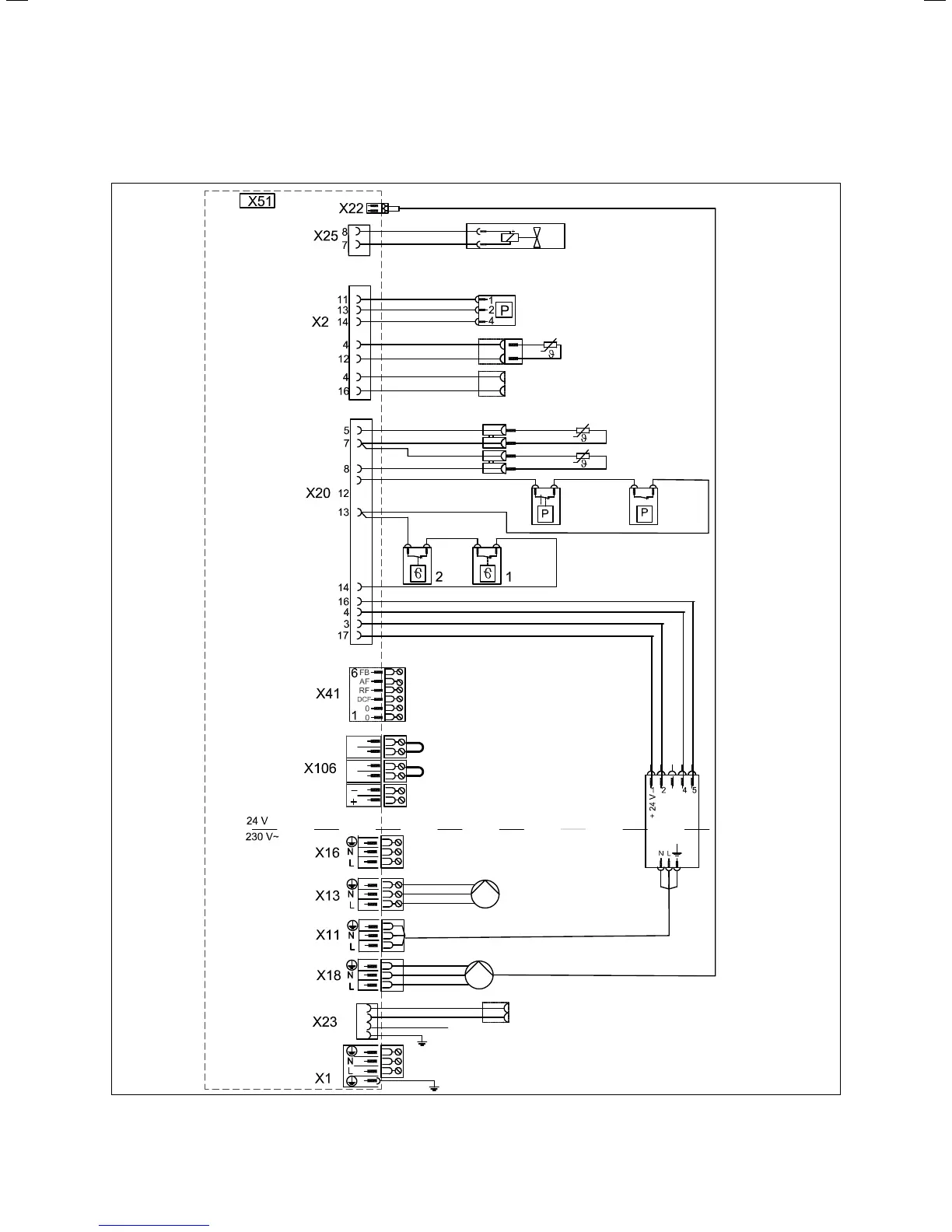
8.6 Connection wiring diagram
Pump PWM signal
Gas valve
Water
pressure sensor
Cylinder sensor (optional)
Cylinder contact
“C1-C2“
Flow sensor
Flow sensor
Water
DD
Flue gas
DD
Safety
cut-out
Safety
cut-out
Remote control circulation pump
External sensor
Flow sensor (optional)
DCF connection
Earth
Earth
Contact thermostat/burner off
Ext. room th. 3-4 (contact, 24 V)
Bus connection
(Controller(room th. digital)
Accessory output
(Select via D.26)
Charging pump
internal pump
Ext. ignition transformer (supply)
Ioni. signal
Unit earth
Mains connection
Unit earth
Fan
Hall signal
PWM
Earth
Display
connection
white
white
red
blue
blue
pink
Edge connector
blue
pink
white
pink
blue
white
grey
turquoise
green
8.4 Connection diagram for the ecoTEC plus electronics box