Replacing components
ecoTEC plus installation and maintenance instructions 0020134823_01 63
15
> Slide the side section to the rear.
> Secure the side section using two screws in the front
lower area and in the upper central area.
> Fit the upper casing (¬section 13.4).
> Fold up the electronics box.
15.3 Replacing the gas valve
2
2
806/5-5
1006/5-5
1206/5-5
1
1
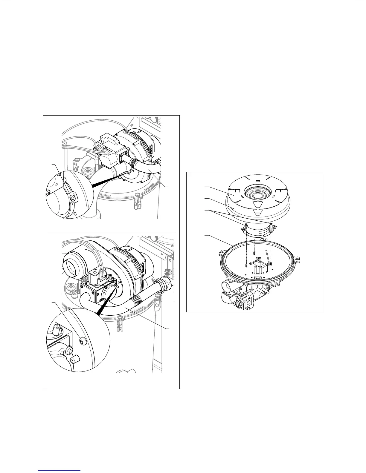
15.2 Replacing the gas valve
> Remove the gas pipe (1) from the gas valve.
> Unscrew the screws (2) from the fan and remove the gas
valve from the fan.
> Replace the defective component.
> Fit the new gas valve in the same position on the fan as
before. Use new seals for this.
> Tighten the screws (1) in a cross-wise pattern.
Torque (only for VU GB 806/5-5 and
VU GB 1006/5-5): 6Nm
Torque (only for VU GB 1206/5-5): 10Nm
> Connect the gas pipe (1) with a new seal to the gas valve.
Torque (only for VU GB 806/5-5): 2Nm
Torque (only for VU GB 1006/5-5 and
VU GB 1206/5-5): 2.8Nm
> After installing the new gas valve, carry out a leak-tight-
ness test (check product function and tightness) (¬sec-
tion 13.5.9) and a gas ratio setting (¬section 13.1.4).
15.4 Replacing the burner
> Remove the gas-air mixture unit (¬section13.5.1).
1
2
4
3
15.3 Replace the burner (example: VUGB806/5-5)
> Remove the ignition and monitoring electrode.
> Remove the seal (4) from the burner door.
> Turn the insulation protection plate (1) to remove it.
> Remove the insulating mat (2).
> Loosen the nuts (3) on the burner.
VU GB 806/5-5: three nuts
VU GB 1006/5-5 and VU GB 1206/5-5: four nuts
> On the VU GB 1006/5-5 and VU GB 1206/5-5 only:
Use a suitable socket (with extension) to ensure that the
burner mat does not become damaged. You must not
use burners that have a damaged mat.
> Remove the burner. When doing so, hold the fan and the
burner door securely.
> Fit the new burner with a new seal.