Replacing components
62 ecoTEC plus installation and maintenance instructions 0020134823_01
15
15 Replacing components
The work described in this section must only be carried out
by a competent person.
> Only use genuine Vaillant spare parts for repairs .
You can find information about available Vaillant genuine
spare parts from the contact address provided on the
reverse of this document.
15.1 Preparing for and completing replacement
work
e
Danger!
Risk of death from electric shock!
Mains connection terminals L and N remain
live even if the continuous voltage on/off
switch is turned off.
> Before carrying out maintenance work
on the boiler, switch the boiler off using
the on/off button.
> Disconnect the boiler from the power
mains by de-energising the boiler using a
partition with a contact opening of at
least 3 mm (e.g.fuses or power switches).
i
When carrying out any repair to the boiler, make
sure that you observe the following instructions
for your own safety and to avoid material dam-
age to the boiler.
> Switch off the boiler.
> Isolate the boiler from the power mains.
> Remove the front casing (¬section4.6).
> Close the gas isolator cock.
> Close the service valves in the heating flow and in the
heating return.
> Close the service valve in the cold water pipe.
> Drain the boiler if you want to replace components that
carry water (¬section13.2.2).
> Make sure that water does not drip on live components
(e.g. the electronics box).
> Use only new seals and O-rings.
Completing replacement work
> Check the boiler for gas tightness.
> Reattach the front casing (¬section4.6).
> Carry out a function test
(¬section 11.5.1 to 11.5.3).
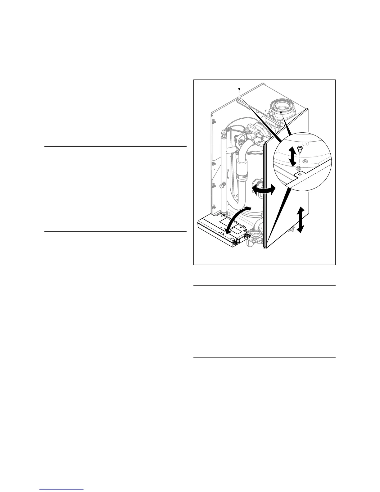
15.2 Removing/fitting the side section
(ifrequired)
15.1 Removing/installing the side section
b
Caution
Risk of material damage caused by
mechanical deformation.
Removing both side sections may cause
mechanical distortion in the product, which
may cause damage to the piping, for exam-
ple, and potentially result in leaks.
> Always only remove one side section –
never both side sections at the same
time.
To remove one side section:
> Tilt the electronics box forward.
> Remove the upper casing (¬section 13.4).
> Hold on to the side section so that it cannot fall, and
unscrew the lower front and upper central screws from
the side section.
> Tilt the side section slightly to the side and pull it out
towards the front.
To fit the side section:
> Push the side section into the bracket. When doing so,
ensure that all straps on the side panel engage with the
rear back wall in order to prevent leaks.

 Loading...


