Hydraulic installation
ecoTEC plus installation and maintenance instructions 0020134823_01 19
6
6.2 Connecting the heating flow and heating
return
b
Caution.
Risk of material damage caused by incor-
rect installation.
Stresses in the supply line may cause leaks.
> Make sure there is no voltage in the sup-
ply lines when they are installed.
b
Caution.
Risk of damage to the service valves.
> Do not solder the connection pieces if
the connection pieces are screwed to the
service valves.
i
Seals made of rubber-like materials may be sub-
ject to plastic deformation, which may lead to
pressure losses.
We recommend using seals made of a paste-like
fibre material.
1
6.1 Installing the heating flow and heating return
> Insert a flat gasket in each.
> Screw the service valves onto the flow and return con-
nection (1) of the pump group.
> Screw the service valves to the customer's installation.
The diameter of the line is 1 1/2".
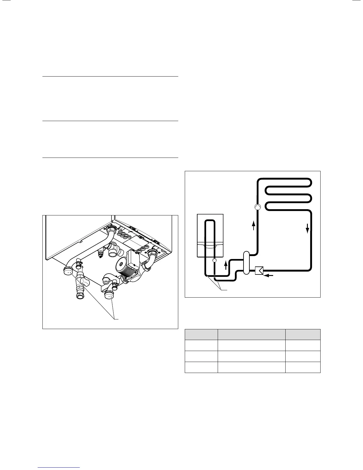
Hydraulic connection
For connection to the system a hydraulic header has to be
used. In difficult cases a plate to plate heat exchanger is
recommended. In all instances the system water should be
adequately treated.
To this end, various plate heat exchangers are available as
accessories, depending on the output of a unit or in cas-
cade connection. The pressure loss is adjusted to the pump
group that is offered as an accessory. The minimum volume
of circulating water is guaranteed in the unit circuit thanks
to the original plate heat exchangers and pump groups, pro-
vided the maximum pressure losses are not exceeded in the
piping.
To prevent contamination, it is recommended that you
install a dirt filter when using plate heat exchangers. This
prevents excessive contamination of the heat exchanger.
Back-purging devices for cleaning the plate heat exchanger
are to be placed on-site.
Ø 1 1/4"
6.2 Diameter of the supply lines
The following remaining feed heads are available at the unit
supply:
Power Description
Remaining feed
head
80 kW Modulating pump
0.042 MPa
(420mbar)
100 kW
Modulating pump
0.026 MPa
(260mbar)
120 kW
Modulating pump
0.024 MPa
(240mbar)
6.1 Remaining feed head pump group
If you are using a plate heat exchanger to hydraulically sep-
arate the system, the following pressure losses must be
maintained:
 Loading...


