Inspection and maintenance
50 ecoTEC plus installation and maintenance instructions 0020134823_01
13
13.3.2 Carrying out electronics self-tests
Menu ¬ Installer level ¬ Test programmes ¬ Electronics
self-test
With the electronics self-test, you can test the relays on the
PCB.
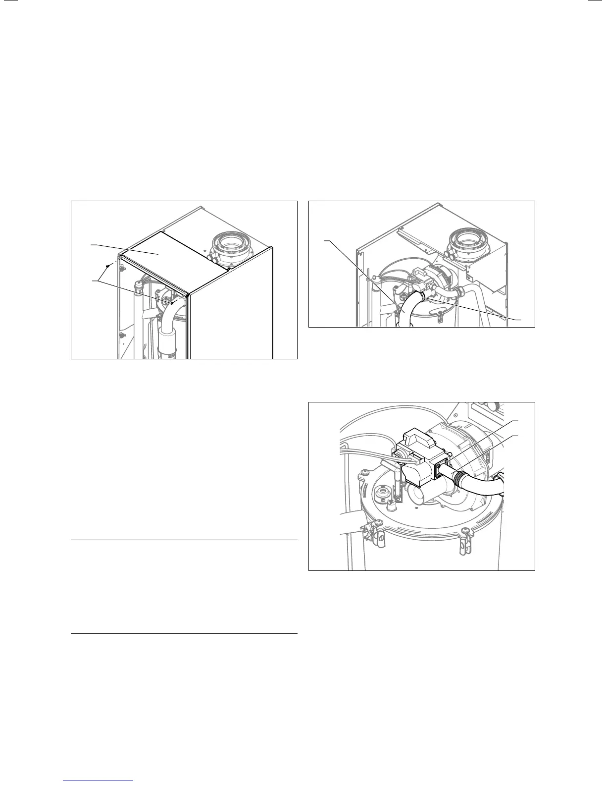
13.4 Removing/fitting the upper casing
2
1
13.3 Removing/fitting the upper casing
To remove the upper casing:
> Unscrew the screws (2).
> Pull out the upper casing (1) towards the front.
To fit the upper casing:
> From above, place the upper casing (2) on the boiler.
> Use the screws (1) to secure the upper casing.
13.5 Carrying out maintenance work
13.5.1 Removing the gas-air mixture unit
a
Danger!
Risk of being burned or scalded by hot
components!
There is a risk of being scalded or burned
on the gas-air mixture unit and on all water-
carrying components.
> Only carry out work on these compo-
nents if they have cooled down.
The gas-air mixture unit consists of four main components:
– Speed-regulated fan
– Air intake pipe
– Gas valve
– Burner
> Switch the boiler off with the on/off button.
> Isolate the boiler from the power mains.
> Close the gas isolator cock on the boiler.
> Close the service valves on the boiler.
> Remove the front casing from the boiler (¬section4.6).
> Undo the upper screws in the side panels.
> Move the side sections slightly outwards.
> Tilt the front unit cover upwards and pull it forwards.
Only on VUGB806/5-5:
2
1
13.4 Remove the air intake pipe (only for VUGB806/5-5)
> Undo the clip (1) on the air intake pipe(2).
> Remove the air intake pipe from the intake port.
For all units:
3
4
13.5 Separate the gas pipework (VUGB806/5-5)