Flue gas installation
ecoTEC plus installation and maintenance instructions 0020134823_01 23
7
2m
H
M
N
H
A
B
C
P
C
S
A
B
B
Q
E
H
D,E
Q
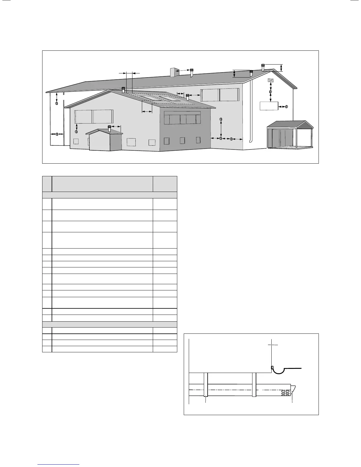
7.2 Opening of the flue pipe
Installation site
Minimum
dimen-
sions
Horizontal flue gas pipes
A Directly below an opening, air bricks, opening
windows, etc.
600 mm
B
(5)
Above an opening, air bricks, opening windows,
etc.
600 mm
C Horizontally to an opening, air bricks, opening
windows, etc.
600 mm
D Below temperature-sensitive building compo-
nents e.g. plastic gutters, down pipes or waste-
water pipes
25 mm
E
(4)
Below eaves, adjacent to wastewater pipes 50 mm
(1)
F Below balconies or car port roofs 25 mm
G
(4)
From a vertical wastewater pipes or down pipes 50 mm
H From internal or external corners 50 mm
H
(2)
From the edges along to a terminal/outside
corner
300 mm
J Opposite an edge or a terminal 2000 mm
J
(2)
From a surface facing a terminal 1000 mm
L From an opening in the car port (e.g. door,
window) which leads into the dwelling
N/A
M Vertical from a terminal 1500 mm
N Horizontal from a terminal 600 mm
Vertical flue gas pipes
P From another terminal 600 mm
Q Above the roof area 600 mm
R
(3)
From adjacent windows that cannot be opened 1000 mm
S
(2)
From an adjacent wall to the flue gas pipe 300 mm
7.1 Position of the opening of a fan-assisted flue gas guiding
Key:
(1)
There should be no ventilation/opening in the eaves within
600mm distance of the terminal.
(2)
These dimensions comply with the building regulations, but they
may need to be increased to avoid wall staining and nuisance
fron pluming depending on site conditions.
(3)
It is recommended that an elbow termination is fitted to direct
the plume away from windows.
(4)
If the pipe is shielded from the heat this dimension may be
reduced to 25mm.
(5)
The flue through the roof should not be located within the
shaded area.
(6)
Is is recommended that the terminal should not be located
below 2m in any occupied space.
BS 5440–1: It is recommended that the fanned flue terminal
should be positioned as follows:
– at least 2 m from an opening in the building directly
opposite, and
– so that the products of combustion are not discharged
directly across a property boundary.
– Dimensions D, E and F:
These clearances may be reduced to 25 mm without
affecting the performance of the boiler. In order to
ensure that the condensate vapour plume does not dam-
age adjacent surfaces, the terminal should be extended
as shown in ¬fig.7.3.
– Dimension H:
This clearance may be reduced to 25mm without
adversely affecting the performance of the boiler. How-
ever, in order to ensure that the condensate vapour
plume does not damage adjacent surfaces, a clearance
of 300mm is preferred.
For IE, recommendations are given in the current issue
of the IS 813.
Balcony/eaves
Gutter
Adequately secured
air/flue gas pipe
The flue pipe must
protrude beyond any overhang
7.3 Opening of the flue gas system under balconies or eaves
 Loading...


