Establishing operational readiness
32 ecoTEC plus installation and maintenance instructions 0020134823_01
9
1
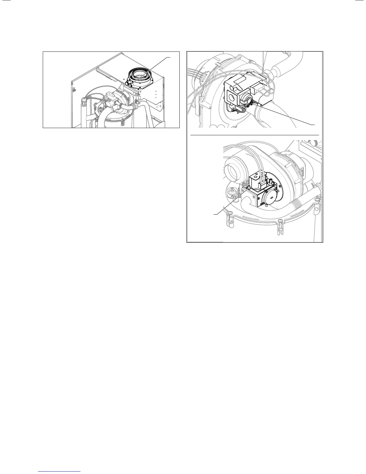
9.3 Flue gas and air analysis points
Key:
1 Flue gas analysis point
2 Air analysis point
> Use the air analysis point (2) to check for flue gas recir-
culation.
> Use the flue gas measuring instrument.
> If you discover CO or CO
2
in the fresh air, search for a
leak in the flue gas system or for flue gas recirculation.
> Eliminate the damage.
> Repeat the above-mentioned test to determine if the
fresh air contains CO or CO
2
.
> If you cannot eliminate the damage, you must not start
up the boiler.
9.6.3 Checking the gas connection pressure
(gasflow pressure)
> Ensure that the gas connection pressure (gas flow pres-
sure) can be still achieved if all other gas-fired boilers in
the dwelling/house are in operation.
> Remove the front casing from the boiler (¬section4.6).
> Close the gas isolator cock of the boiler.
i
Permissible gas connection pressure (gas flow
pressure) for natural gas operation:
2 kPa (20mbar) to 2.5kPa(25 mbar)
1
1
806/5-5
1206/5-5
1006/5-5
9.4 Measuring the gas connection pressure (gas flow pressure)
> Undo the sealing screw of the measuring nipple (1)
(lower screw) at the gas valve using a screwdriver.
> Connect a digital pressure gauge or U tube manometer
to the measuring nipple (1).
> Open the gas isolator cock of the boiler.
> Start the boiler by activating check programme P.1, as
described in ¬section14.4.
> Turn the room thermostat fully up to that the maximum
heat in the heating installation can be shown.
> Measure the gas connection pressure in comparison with
atmospheric pressure.