9Installation Manual for VR 32 GB
5 Electrical installation
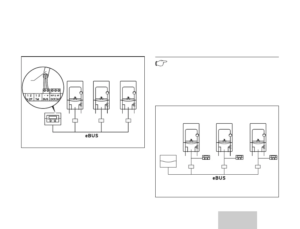
5.1 Connecting the bus coupler (cascade)
1
VR 32 VR 32 VR 32
Fig. 5.1 Connecting the bus coupler (cascade)
• Connect the bus line (1) in the bus modular
controller (terminal designation: BUS).
• In combination with vrnetDIALOG only:
Connect the bus coupler to the bus line in
the vrnetDIALOG.
Note
The eBUS can be branched at any
part of the system.
5.2 Connecting the bus coupler
(system 1 - 16)
vrnetDIALOG
VR 32 VR 32 VR 32
Fig. 5.2 Connecting the bus coupler (system 1 - 16)
Electrical installation 5