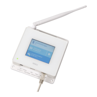
2.2 AP10 Parts
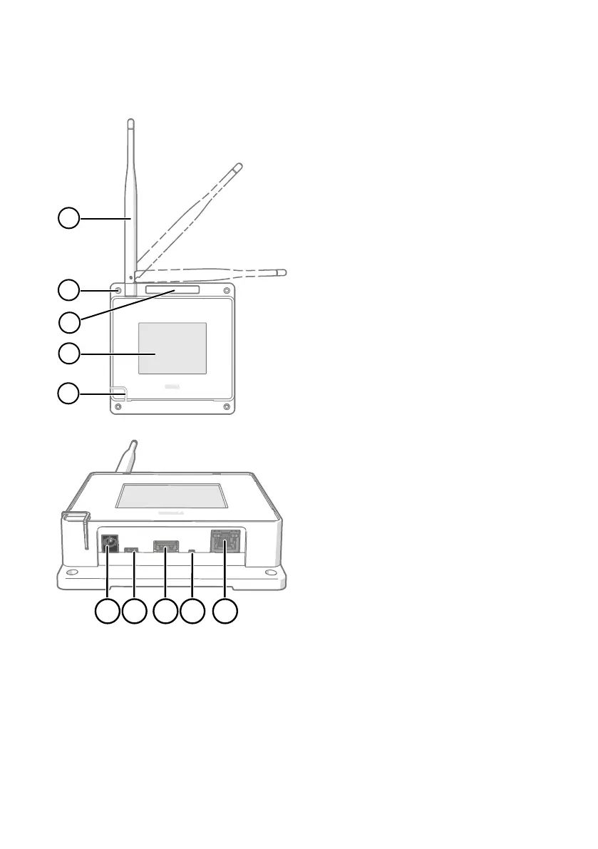
Figure 2 Front
1 Antenna. Can be rotated and tilted.
2 Screw holes for mounting (4 pcs),
Ø 3.2 mm.
3 Ventilation hole. Do not cover.
4 Touchscreen.
5 Status LED:
Green Normal operation
Blue Installation mode active
Red Error - check status
Figure 3 Connector Panel
1 Power supply connector (10 ... 30
VDC).
2 Service port (micro-USB).
3 USB port for hardware expansion
(USB type A).
4 Reset button. Push to restart, push
and hold to revert AP10 to factory
settings.
5 RJ-45 Ethernet port. Can be powered
by Power over Ethernet (PoE).
AP10 User Guide M211860EN-A
8