List of Figures
Figure 1 AP10 in the viewLinc Monitoring System....................................................7
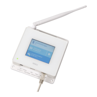
Figure 2 Front......................................................................................................................8
Figure 3 Connector Panel................................................................................................ 8
Figure 4 Rear.......................................................................................................................9
Figure 5 AP10 Remote Management using viewLinc Enterprise Server........... 12
Figure 6 AP10 Properties in viewLinc..........................................................................13
Figure 7 AP10 Mounting Methods................................................................................21
Figure 8 AP10 Screw Mounting Dimensions.............................................................22
Figure 9 Touch Interface Home Screen......................................................................23
Figure 10 Touch Interface Data Logger Information Screen..................................24
Figure 11 Touch Interface Settings Menu....................................................................24
Figure 12 Web Interface System Summary Screen.................................................. 26
Figure 13 Web Interface Data Loggers Screen.......................................................... 27
Figure 14 Web Interface Network Settings.................................................................27
Figure 15 Web Interface DNS, NTP, and VaiNet Settings Screen..........................28
Figure 16 Web Interface viewLinc Settings Screen..................................................28
Figure 17 Web Interface Installation Mode Settings Screen..................................29
Figure 18 Web Interface Security Settings Screen...................................................29
Figure 19 Web Interface Display and LED Settings Screen................................... 30
Figure 20 Web Interface Backup and Restore Screen.............................................30
Figure 21 Web Interface Firmware Update Screen................................................... 31
Figure 22 Web Interface Restart and Reset Screen..................................................32
Figure 23 Web Interface Support Screen Screen......................................................33
Figure 24 AP10 Access Point Dimensions................................................................... 42
List of Figures
3