Chapter 6 ________________________________________________ Maintenance
VAISALA__________________________________________________________43
0205-019
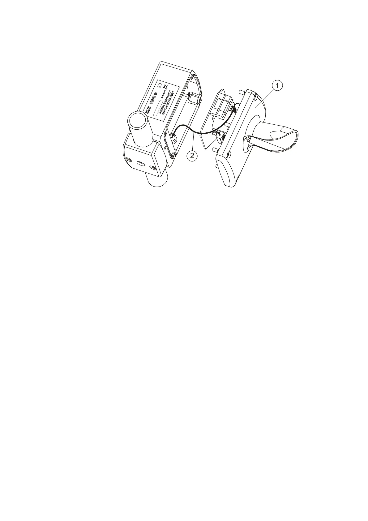
Figure 10 Removing the LMM101 Assembly
The following numbers refer to Figure 10 above:
1 = LMM101 assembly
2 = Signal and Power Cable
4. Connect the signal and power cable into the new
LMM101 assembly. See Figure 11 on page 44. The
empty connector slots should face the top of the board.