List of figures
Figure 1 Connecting RFL100 to the viewLinc Monitoring System....................... 8
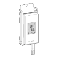
Figure 2 Front and display............................................................................................. 10
Figure 3 Under the silicone plug.................................................................................. 10
Figure 4 Rear and inside.................................................................................................. 11
Figure 5 Mounting bracket..............................................................................................11
Figure 6 Alarm indicators on RFL100 display...........................................................16
Figure 7 RFL100 with high alarm active on channel 1.............................................17
Figure 8 RFL100 with high-high alarm active on channel 1.................................. 17
Figure 9 Detection of a new RH + T probe................................................................22
Figure 10 RFL100 mounting methods......................................................................... 26
Figure 11 Probe holder ASM213382 parts...................................................................28
Figure 12 HMP110 probe in probe holder ASM213382............................................. 28
Figure 13 HMP110 probe...................................................................................................29
Figure 14 HMP115 probe...................................................................................................29
Figure 15 TMP115 probe................................................................................................... 30
Figure 16 Detection of a new RH + T probe shown on display.............................. 31
Figure 17 RFL100 remote management using viewLinc Enterprise Server...... 33
Figure 18 RFL100 device properties in viewLinc...................................................... 34
Figure 19 HMP115 probe in Insight software...............................................................36
Figure 20 Connecting probe to insight........................................................................ 37
Figure 21 Adjusting relative humidity measurement in Insight............................ 52
Figure 22 RFL100 dimensions with mounting bracket............................................68
Figure 23 RFL100 dimensions without mounting bracket..................................... 69
Figure 24 RFL100 mounting bracket dimensions..................................................... 69
Figure 25 HMP110 probe dimensions............................................................................70
Figure 26 HMP115 probe dimensions............................................................................70
Figure 27 TMP115 probe dimensions.............................................................................70
List of figures
3

 Loading...