Chapter 3 _______________________________________________________________ Installation
VAISALA _______________________________________________________________________ 31
Connections
WS425 has a 16-pin circular plastic connector (male) at the bottom of the
sensor. A cable connector of type AMP206037-1 can be used to attach
wires to the sensor pins.
CAUTION
When WS425 is installed upside down, always make sure the connector
is protected from rain and snow.
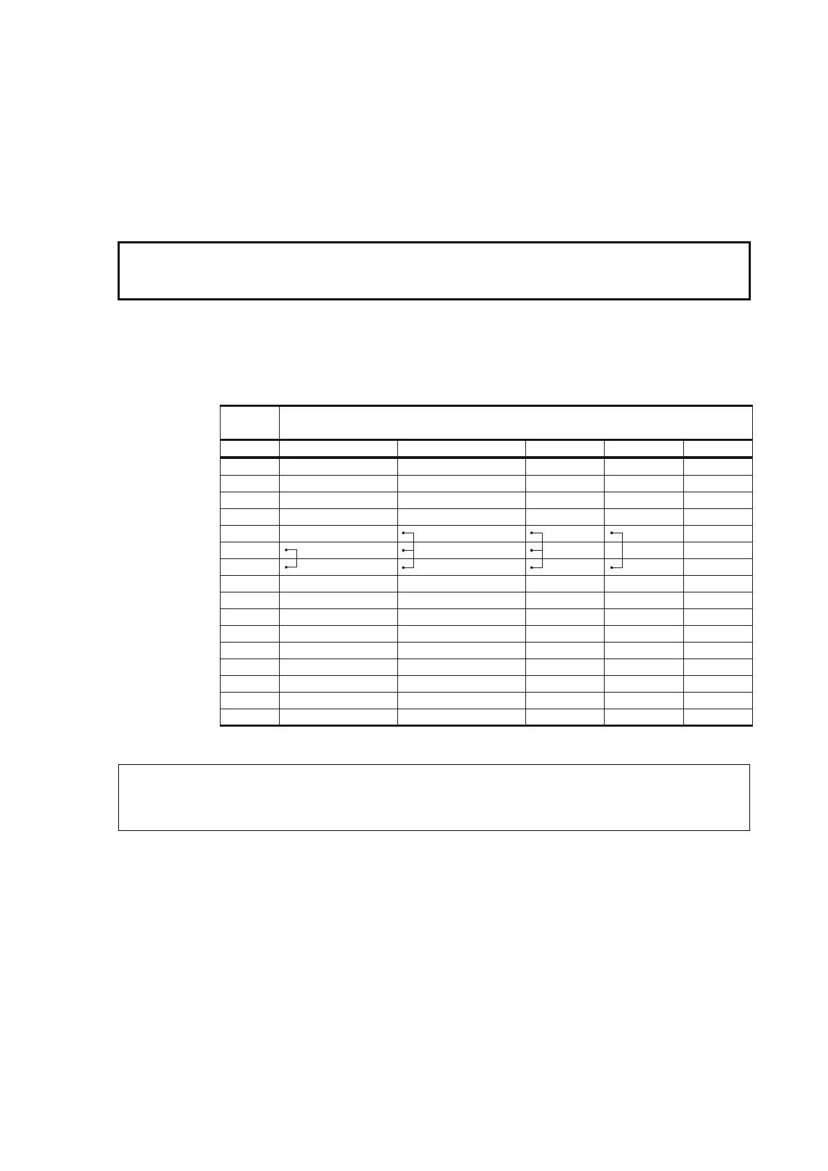
Table 8 below illustrates usage of the pins with different protocols.
Table 8 WS425 Sensor Pins
NOTE
The short-circuits between pins 5, 6, and 7 are required for selecting the
protocol.
Sensor
Pin No.
Protocol
RS-232 RS-422 RS-485 Analog SDI-12
1 GND GND GND GND GND
2 GND GND GND GND GND
3 GND GND GND GND GND
4----
5- -
6 -
7 GND
8 GND GND GND GND GND
9 Data out (TxD) Data out (T-) RT- - -
10 Data in (RxD) Data in (R-) RT- - SDI data
11 +12 VDC +12 VDC +12 VDC +12 VDC +12 VDC
12 - Data out (T+) RT+ WD Vref in -
13 - - - WD Vout -
14 - Data in (R+) RT+ WS Fout -
15 - - - WS Vout -
16 +36 VDC +36 VDC +36 VDC +36 VDC +36 VDC