USER'S GUIDE____________________________________________________________________
70 __________________________________________________________________ M210361EN-E
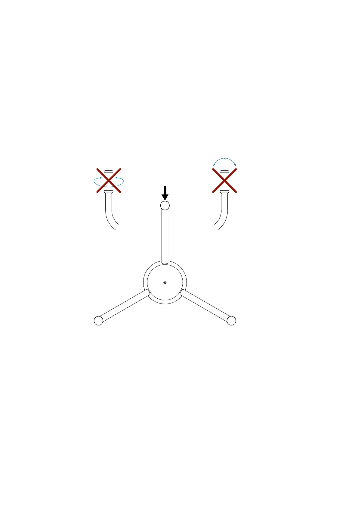
3. Do not strike or bend the transducers. Striking or bending the
transducers will destroy the array of the ultrasonic wind sensor. All
the transducers should be parallel to each other. For the correct
alignment, see Figure 13 below.
4. The verifier should slide over the transducers without excessive
force. This validates that the mechanical spacing of the transducers
is within specifications.
5. Do not scrape or touch the transducers with sharp objects. Cutting
the silicon rubber sleeve on the transducer affects the acoustical
matching layer of the transducer and destroys the array of the
ultrasonic wind sensor. The silicon rubber transducer sleeve must
not be damaged.
0506-020
Figure 13 Solder Spot and Sensor Handling