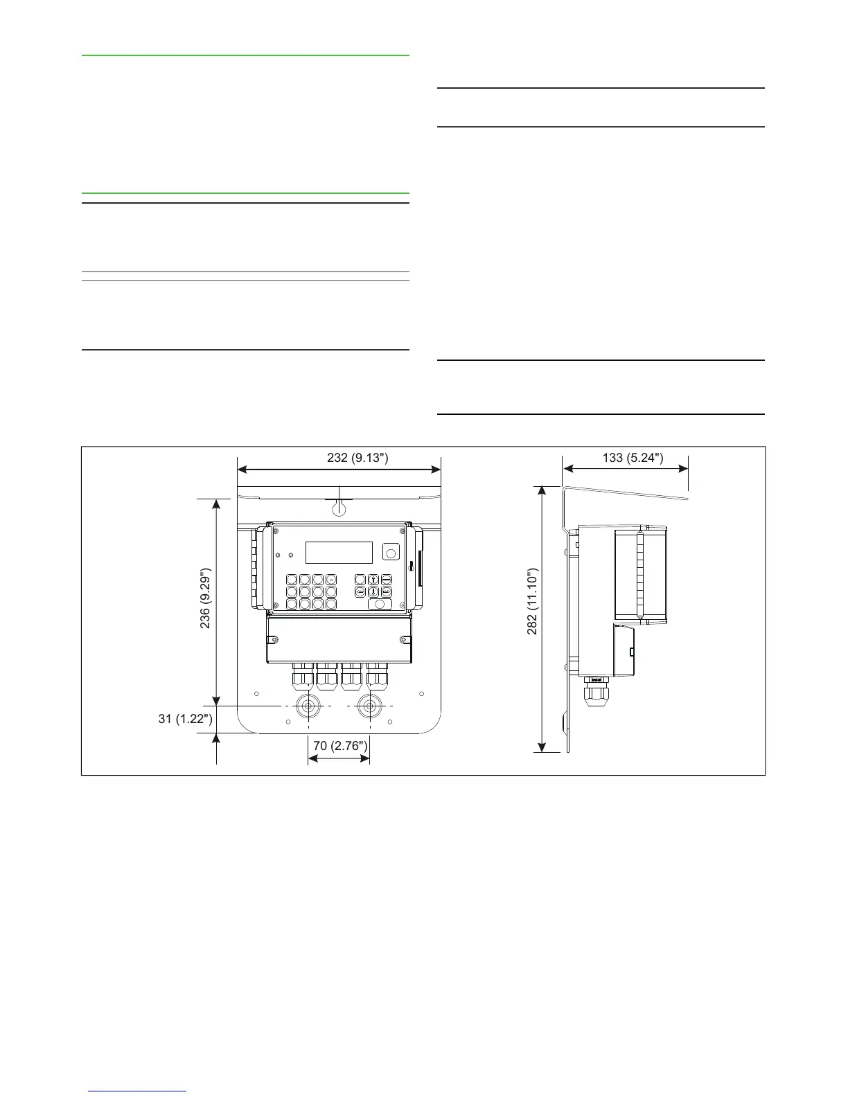
3.6. Transmitter Central Unit (TCU) and shield
The TCU is delivered attached to the shield. The shield
is attached to the wall with three mounting screws in a
place that is easily accessed.
When selecting a place for the TCU, remember that
the sensor cable is 10 m long. Figure 15 shows shield
mounting dimensions.
3.7. Electrical Connections
NOTE: When connecting the power supply cables, check
that the cables are de-energized. Perform and check all
connections before you connect the power supply to the
cables.
NOTE: If the TCU has been switched off for a long time,
it may take a few minutes for text to appear on the dis-
play. This is due to the charging of the device's internal
back-up battery.
Sensor Cable
NOTE: In a normal delivery, the sensor cable is already
connected to the TCU.
1. Insert the end of the sensor cable that has no
connector into the TCU connector casing through
the inlet and connect it as shown in Figure 17. The
protective shields are connected as follows:
- Twisted pair lines' intertwined protective shields
(cable 3) are connected to adaptor GND together
with cable 2.
- The sensor cable's protective shield (cable 5) is
connected to adaptor SC SHIELD (Sensor Cable
Shield).
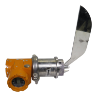
2. Bring the sensor cable to the sensor unit and
connect its adaptor to the adaptor in the base plate
of the sensor electronics.
NOTE: Do not place the sensor cable on cable shelves
that contain cables of motors, pumps or other electrical
cables.