11.4. Antennas, Fork Sensor
NOTE: Before removing the antennas, check that the
process pipe is empty and unpressurized and that remov-
al is safe.
Removal:
1. Remove the sensor electronics as described in
Chapter 11.1.
2. Remove the antenna cable of the antenna that is
being replaced as described in Chapter 11.2.
Flush-mounted antenna:
3. Unscrew two M8 Allen screws to remove the an-
tenna from its mounting clamp.
4. Pull the antenna out of the inlet hole and remove
the O-ring.
5. Unscrew two M4 screws to remove the clamp from
the antenna.
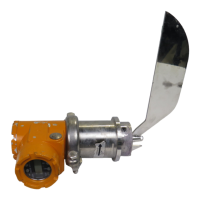
Probe antenna:
6. Use socket key OUL00325 and a 13mm ring
spanner to remove the probe antenna.
Installation:
Flush-mounted antenna:
1. Attach the mounting clamp to the antenna with two
M4x16 screws with washers.
2. Clean the sealing surfaces of the antenna installa-
tion hole using e.g. isopropanol.
3. Place a new O-ring into the installation hole against
the collar.
4. Place the antenna into position. Attach it with
M8x20 Allen screws and washers using a 6mm
Allen wrench. Use locking medium Loctite 270 on
the threads.
5. Tighten the antenna's mounting screws to 19 Nm
torque.
Probe antenna:
1. Clean the sealing surface with e.g. isopropanal.
2. Place a new O-ring into the sealing groove.
3. Put locking medium Loctite 270 on the threads.
4. Screw the probe antenna into the sensor body
using socket key OUL00325 to 10 Nm torque.
5. Install the antenna cable(s) as described in
Chapter 11.2.
6. Attach the sensor electronics as described in
Chapter 11.1.
11.5. Antennas, FT Sensor
NOTE: Before removing the antennas, check that the
process pipe is empty and unpressurized and that remov-
al is safe.
Removal:
1. Remove the sensor electronics as described in
Chapter 11.1.
2. Remove the antenna cable as described in 11.2.
3. Remove the antenna's six mounting screws with
a 5mm Allen wrench. In the FT-100 model there
are four mounting screws and the washers are
self-sealing.
4. Pull the antenna out of the inlet hole and remove
the O-ring.
5. Remove the antenna from the flange by unscrew-
ing two M4 screws.
Installation:
1. Attach the antenna to the flange with two M4x12
screws with washers.
2. Clean the sealing surfaces of the antenna installa-
tion hole using e.g. isopropanol.
3. Place a new O-ring into the installation hole against
the collar.
4. Put locking medium Loctite 270 onto the flange's
six mounting threads.
5. Check that the antenna flange O-ring is in place
and then insert the antenna into place in the an-
tenna coupling.
6. Tighten the antenna's six M6x16 mounting screws
and washers with a 5mm Allen wrench to 8 Nm
torque. In the FT-100 model there are four screws
and the washers are self-sealing.
7. Connect the sensor cable and the sensor electron-
ics back in reverse order.
Installation & Owner’s manual OUL00298 V2.3 EN
49
Valmet Mircowave Consistency Transmitter