2323
Appliance Preparation
Top Heat Shield & Stand-offs Fitting
See fi gures 24 & 25.
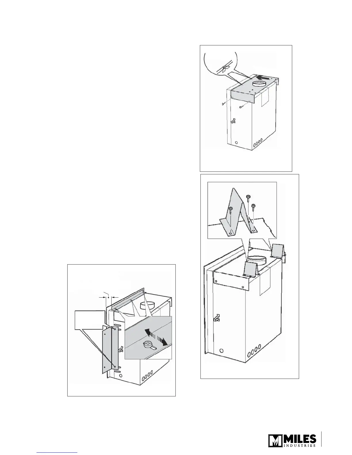
If installing appliance with top vent outlet, remove
the plate covering the vent hole in the top heat shield
by unscrewing four screws. If installing with rear vent
outlet, the plate must remain, covering the hole.
Remove the screws at the top rear corner of the case
sides.
If top vent outlet, locate the heat shield over the vent pipe
adapter.
Support the front of the shield on the two angle supports.
Secure the shield to the case sides by refi tting the two
screws at the top rear corners and by two screws from
the pack fi tted near the front.
Bend the two top rear stand-offs and fi t to the heat shield
with three screws each. See fi gure 25.
NOTE: Zero clearance stand-offs and shield supplied with
the heater are not required for the co-linear application.
Support Angles Fitting
See fi gure 26.
The distance from the wall angles to the front face of the
heater case is adjustable between 3/8” (10 mm) and 1-3/16”
(30 mm) to allow for a range of wall fi nish material thickness
(e.g. tile, etc.).
Fit the top angle support to the case top with three
screws.
Fit the two side angle supports with two screws each. Fit
the screws from inside the heater case.
1.
2.
3.
4.
5.
6.
1.
2.
Wall finish material
thickness (tile, etc.)
3/8” - 1-3/16”
(10-30 mm)
Fit screws
from inside
case
Figure 26 Support angles
Shield to rest
on 2 supports
Push shield
forward
Figure 24 Heat shield
(shown for top vent outlet)
Figure 25 Top & rear stand-offs
 Loading...