2424
Type “A” Maximum opening
Type “A” Minimum opening
Type “B” & “C”
Hole(s) at top
Type “A” Type “B” Type “C”
Vent terminal
Appliance
vent outlet
Vertical vent pipe run
Use
restrictor
type
Port
opening
set at
Horizontal
through wall
with vertical rise
Top Less than 3’ (91 cm) A Maximum
From 3’ (91 cm) to 6’
(183 cm)
A Minimum
Rear Less than 3’6” (107 cm) A Maximum
From 3’6” (107 cm) to 6’
(183 cm)
A Minimum
Vertical through
roof
Top or rear Less than 20’ (6.1 m) B
N/A
From 20’ (6.1 m) to
40’ (12.2 m)
C
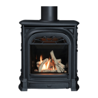
Figure 27 Restrictor identifi cation
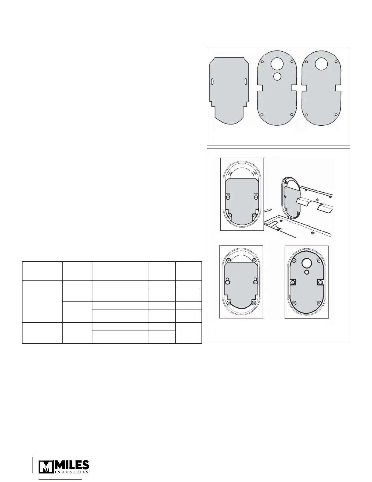
Figure 28 Restrictor locations
Appliance Preparation
Attaching Air Restrictors
No restrictors are required for appliances which only
have horizontal vent run. If installing an appliance which
has a rear vent outlet connection and no vertical vent
pipe rise, ignore this stage.
There are three types of restrictors supplied with each #534
engine unit. They are identifi ed in fi gure 27.
Type “A” is for horizontal vent termination.
Types “B” & “C” are for through-the-roof termination.
The restrictors cover part of the openings in the fi rebox rear
wall ports. See fi gure 28.
The correct restrictors to be fi tted for each type of installation
are shown in the table below.
To fi t type “A” restrictors, remove the center screws
from the rear ports and fi t the restrictors using these
screws.
To fi t types “B” or “C” restrictors, remove the top and
bottom screws from the rear ports and fi t the restrictors
using these screws.
To set the restrictors at maximum port opening, slacken
the bottom screws in the ports, slide the restrictors down as
far as possible and tighten the screws over the restrictors.
To set the restrictors at minimum port opening, slide the
restrictors up as far as possible and tighten the screws.
•
•
•
•