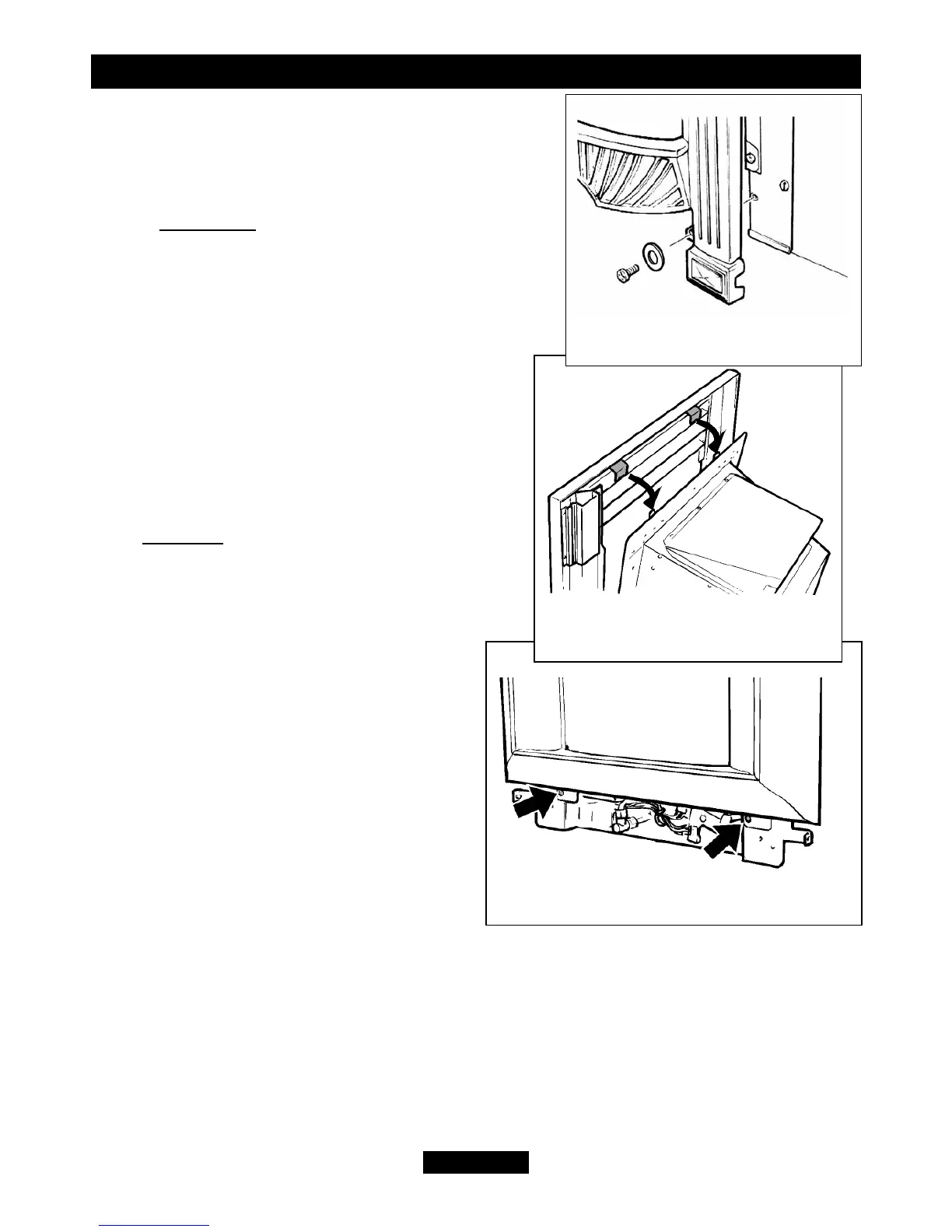
front casting sideways, if necessary, to align the
bottom fixing holes with those in the convection box.
Fix the bottom of the casting to the convection box
with two screws and washers (See figure 38).
12.2.3 Icon fascia
Place the fascia against the fireplace front surface
so that the two retaining plates at the back of the
fascia are directly above the two upper retaining
brackets at the top of the convection box. Lower the
fascia unit making sure that the ears on the fascia
retaining plates locate fully over the sides of the
convection box brackets (See figure 39).
Swing the bottom control linking bar towards the
centre of the fire to clear the right side of the
fascia. Fix the bottom of the fascia unit to the
convection box with two screws (See figure 40).
12.3 All fascia
Align the hole near the bottom of the control
linking bar with that in the control pivot bracket.
Join them with the knurled shouldered screw and
screwdriver - NOT finger tight only (See
figure 41). Make sure that the isolating
valve is closed. Slide the control knob fully
from top to bottom and back to make sure
that the slide and pivot mechanisms move
smoothly. Note that some resistance should
be felt when the control knob reaches the
“burner fully on” position.
Important note: If the slider jams or fails
to operate remove the fascia and ensure
that the right hand screw that secures
the burner module to the convection box
is screwed in fully.
© GDC Group Ltd. 2011
Page 34
INSTALLER GUIDE
Figure 40. “Icon” fascia bottom location
Figure 39. “Icon” fascia top
location
Figure 38. Adorn fascia bottom
fixing.