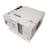
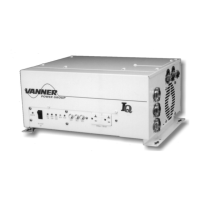
Theory of Operation
- 30 - IQ SERIES OWNERS MANUAL
5.3 Automatic Power Transfer Switch Theory of Operation
The function of the Automatic Transfer Switch is to automatically accept AC input power from shore or generator,
and use this power to operate inverter loads and to provide power for battery charging. Upon loss of AC input
power, the transfer switch automatically switches the AC loads back to inverter power. Transfer time is
approximately 30 milliseconds (0.030 seconds). The 0.030 second transfer time allows all but the most sensitive
loads to transfer from inverter power to shore power and back to inverter power without interruption.
AC input voltage and frequency are monitored for proper tolerance at all times on AC1. When the AC input is
within tolerance for approximately 5 seconds, the power is passed through to AC3 output circuit and the IQC
automatically switches from inverter mode to battery charger mode. The IQC automatically switches back to
inverter mode when input power is disconnected or when input power is no longer within tolerance. See IQ Series
Specifications page for AC input voltage and frequency tolerances. The 5 second delay occurs only if the inverter
is fully ON when input power becomes available. There is no 5 second time delay if the inverter is in the ‘Load
Demand Mode’ when input power becomes available.
Switch 6 on the Programming Switch allows the user to select either 90 AC input volts or 77 AC input volts to be
the Low AC Input Voltage switchover tolerance value. Set switch 6 to match the quality of AC being supplied. HI
(90 VAC) is generally used on more stable AC power (Residential or Industrial Supplies). LOW (77VAC) is used
with less stable AC power (motor generator, solar, rural supplies).
For all IQC models, the factor that determines whether the unit is in ‘inverter mode’ or ‘battery charger mode’ is
the presence or absence of ‘in-tolerance’ input power. Whenever ‘in-tolerance’ input power becomes available the
IQC automatically switches from inverter mode to charger mode.
The transfer switch switches both hot and neutral. For safety purposes the inverter output neutral (terminal #8) is
connected to the inverter chassis ground only when the unit is in inverter mode. This is a requirement of the
National Electric Code for all systems of this type that neutral should be connected to ground only at the source of
AC power, which is the inverter when in inverter mode. When an external AC input (shore power, generator) is
available, the IQC Transfer Switch system breaks the connection between neutral and inverter chassis ground.
The neutral-to-ground connection for passthrough power is then provided by the AC input source.