Theory of Operation
IQ SERIES OWNERS MANUAL - 31 -
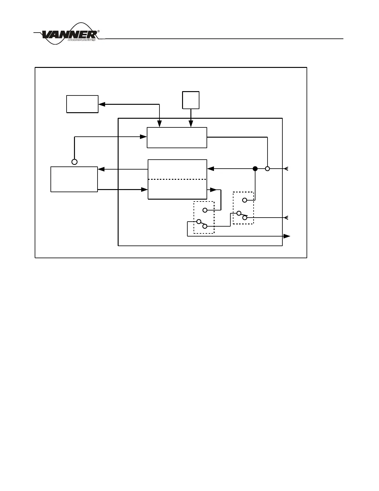
Figure 6 AC Power Transfer Switch
5.4 Automatic Power Management (APM) Theory of Operation
‘AC power for battery charging’ enters the IQC through AC1. ‘AC power for passthrough to AC loads’ enters
through AC1 when AC2 is not used. The Automatic Power Management circuit monitors total AC amps entering
through AC1 and, when necessary, reduces the battery charger’s AC power consumption so that total AC1 amps
do not exceed the APM Setting. The default APM Setting is 30 amps. The APM circuitry does not limit AC power
passing through to AC loads. The battery charger will draw approximately 27.5 AC amps from shore power when
the 12 volt charging output is 120 amps. A lower charger setting will draw proportionally lower AC input amps.
When shore power is connected to both AC1 and AC2, then AC1 only supplies power to the battery charger and
AC2 only furnishes power to passthrough to the AC loads. Automatic Power Management still applies to AC1,
controlling the battery charger power consumption, but without being affected by power passing through to the AC
loads.
AC1 is rated 30 amps and is protected by the 30 amp input circuit breaker CB1. When AC2 is not used it is
expected that the AC current passing through to AC loads combined with AC current needed for battery charging
may exceed 30 amps. The APM circuit prevents the 30 amp breaker from tripping by reducing the battery charger
output as needed until either the AC1 input current is less than 30 amps or until the battery charger power is zero.
The optional D07934 Remote APM Panel allows adjustment of the APM Setting to values lower than 30 amps.
For inverter/charger serial numbers up to 02154-049638 the Remote APM Panel selects APM Settings of 30
OPTIONAL
REMOTE
PANEL
OPTIONAL BATTERY
TEMPERATURE SENSOR
MICROPROCESSOR
CONTROLLER
BATTERY
BATTERY CHARGER
INVERTER
DC
IN
DC
OUT
AC
OUT
AC
IN
APM
SENSE
30 AMP
AC
INPUT 1
AC
INPUT 2
AC
OUTPUT
OPTIONAL
APM
PANEL
SW1
SW2
A
B
A
B
FIGURE 6 - AC Power Transfer Switch