Page 17
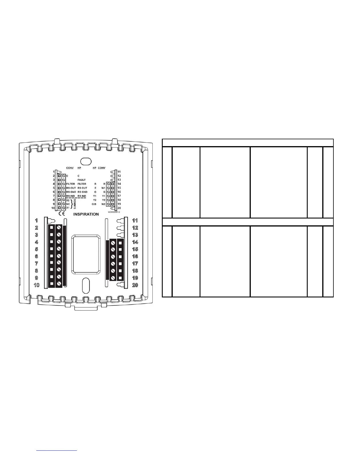
Wiring Configuration
This thermostat should be wired by a licensed technician familiar with HVAC installation.
111
2 CCommon 12
313
4 FILTER Filter Power(2 4VAC ) R 14
5 RSOUT OutdoorSensor 1'stStageHeat W1 15
6 RSGND SensorG round F a n G 16
7 RSIN D IndoorSensor 1'ststageC ooling Y1 17
8 X2 C ommunica tion 2'nd StageC ooling Y2 18
9 NC NoC onnection 2'ndStageHeat W2 19
10 X1 C ommunic ation 20
111
2 C C ommon 12
3
FAULT HeatPumpFault 13
4 FILTER Filter Power(2 4VAC ) R 14
5 RSOUT OutdoorSensor AuxiliaryHeat E 15
6 RSGND SensorG round F a n G 16
7 RSIN D IndoorSensor 1'stStageHeatPump Y1 17
8 X2 C ommunica tion 2'ndS ta ge He a tP ump Y2 18
9 NC NoC onnection C ha ngeov e rValve O/B 19
10 X1 C ommunic ation 20
CONVENTIONALSYSTEMS(C ON V)
HE ATPUMPSYSTEMS(HP )