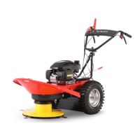
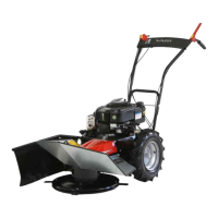
BDR-720 Adela PRO
3.5.3.3 LUBRICATION POINTS
A spray oil that repels water and dust particles or a liquid "white" vaseline spray is suitable for lubrication. Of the solid
lubricating greases, any lubricant intended for lubrication of water pumps is fully sufficient. However, its application usually
requires the dismantling of the corresponding slide assembly.
Lubrication point -
description
Interval within
season
After
season
Lubrican
t
Figure Note
Bowden cables / levers at least 2x Yes Oil
Fig. 13, Fig. 20, Fig. 21
Cable entry into the bowden
cable / pins
Cutting disc drive pulley
housing
every 10 hours Yes
Oil/
grease
Fig. 14
Pulley pin - the cutting disc cover
must be removed
Travel clutch pulley - Yes
Oil/
grease
Fig. 15
Pulley pin - shift lever and
handlebars must be removed.
Brake key - Yes Oil
Fig. 14
Spanner pin - the cutting disc
cover must be removed
Bowden cable divider - Yes Vaseline
Fig. 16
Bowden cable slider - it is
necessary to click the lid of the
switchboard.
Table 37: Lubrication intervals
3.5.3.4 TYRES
• Check the tyre pressure before working with the machine.
• If there is a permanent tyre pressure leakage, make sure that there is no defect on the tyre tube – repair it if necessary.
If you are not sufficiently manually skilled, have the operations done by an authorized service centre.
• Keep the same pressure in the left and right wheels – the machine better holds a straight track.
Do not exceed the maximum tyre pressure – there is a risk of the tyre explosion!
MAXimum tyre pressure: 20 PSI (138 kPa or 1.38 bar or 1.36 atm or 0.14 MPa)
Operating
84
tyre pressure: 18 PSI (124 kPa or 1.24 bar or 1.22 atm or 0.12 MPa)
• Before the machine is put away for a longer time, refill the pressure to MAX.
Whenreplacing a wheel or tyre due to tread wear or an irreparable defect, always replace the wheels or tyres onboth sides
of the machine. The different diameter of the new and worn wheel will cause the machine to turn spontaneously and the
vegetation will not be cut evenly.
3.5.4 WORKING BLADES SHARPENING AND REPLACEMENT
In the case of any unprofessional repair of the blades using other than original parts, the manufacturer is not
liable for any damages on the machine or caused by your machine. The blade is embossed with a sign that
indicates the manufacturer and is a check mark that the blade is an original spare part.
If you are not sufficiently manually skilled, have the operations done by an authorised service centre.
If the cutting edges are worn or blades are damaged, causing machine vibrations, the cutting edges should be restored or the blades
replaced
85
.
The machine must be placed on a hard horizontal surface and must be secured so that there is good access to the
blade and machine would not start moving unexpectedly.
Take special care when removing the blades. Blade cutting edges are sharp. Protect your hands with working
gloves.
Disconnect the ignition spark plug cable.
1)
Fig. 18
Hold the upper disc, so that it does not rotate, and use a No. 15 or No. 16 socket wrench or socket head to remove the
blade screw connection. First, unscrew the nut 2 , then the screw 3 .
2) Remove the blade 1 and blade mount parts ( 4 and 5 ) from the cutting disc. Straighten the edges and sharpen the blade
cutting edges. The inclination of the sharpened edge should be 30° with respect to the blade’s bottom plane.
3) Make sure all the blade mounting parts feature no visible damage. Otherwise, replace a damaged with a new one.
Rubber ring
6
does not need to be reassembled, it only prevents the knives from rattling on new machines, it does not
affect the cutting quality.
4) Screw the blade screw assembly back in. Tighten the screw 3 firmly
86
. Lock the screw with its nut 2 .
If any blade is bent or excessively worn, you must always replace all the cutting disc blades!
84
If the tyre pressure is lower than indicated, the tyre structure will be damaged, and its service life will be significantly reduced.
85
The blades have two edges - they may be rotated as needed. In any case, the blade must be undamaged.
86
Insufficient screw tightening leads in most cases to the destruction of the hardened pad around which the blade rotates.
49
Revize 07/2021