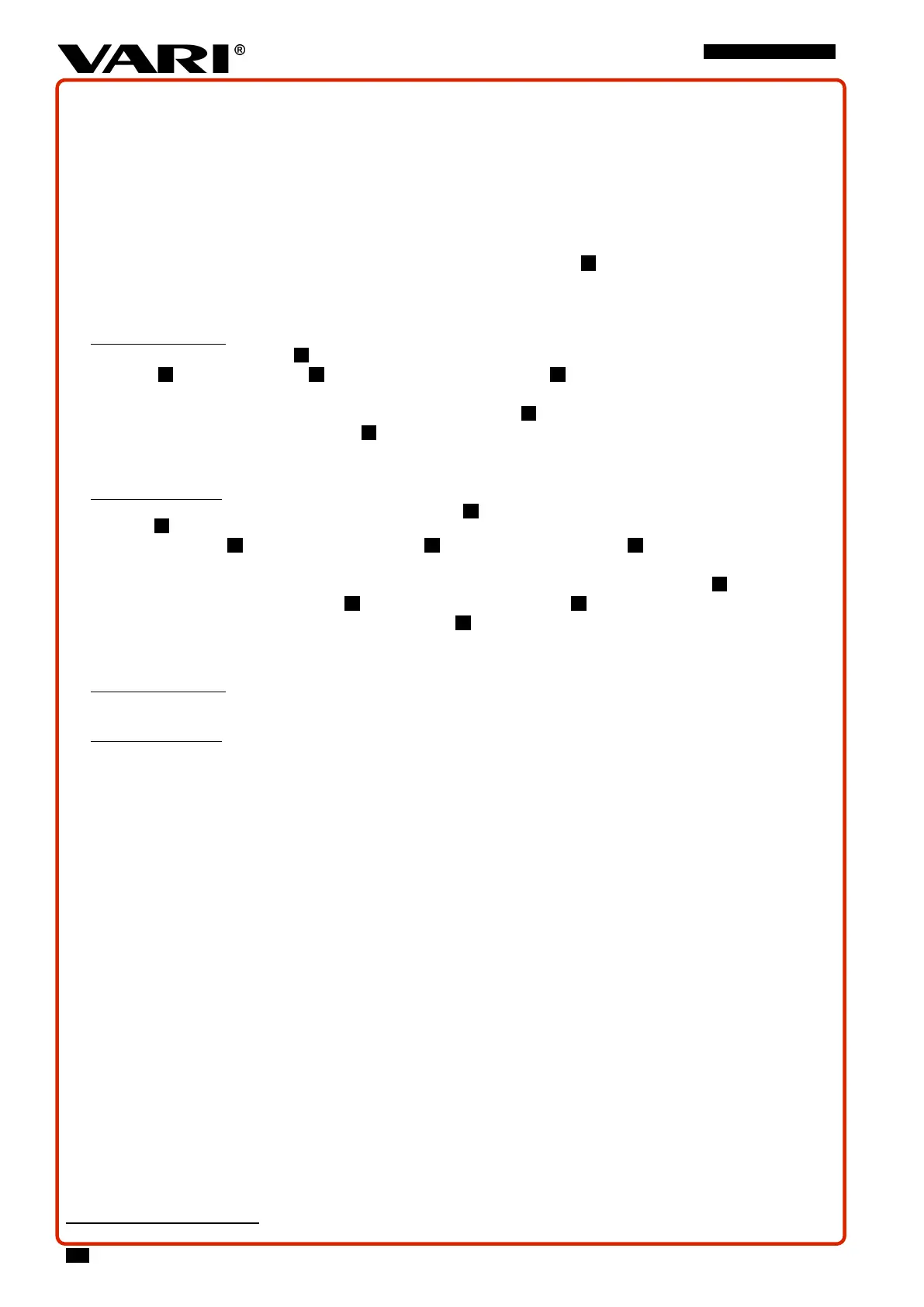
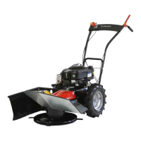
BDR-720 Adela PRO
3.5.5 BELT GEARS
Perform regular belt inspections. Always replace the V-belts with new ones
87
if cracks, tears or cracks appear on the surface
of the belt or if the belt is so worn by operation that it can no longer be tightened with the tension pulleys.
The factory adjusting of the tension pulleys must be checked after app. first 5 hours of operation when the belt has been run
in, to prevent belt damage due to its elongation and insufficient tensioning by it tension pulley.
If you are not sufficiently manually skilled, have the operations done by an authorised service centre.
3.5.5.1 V-BELT CHANGE
While changing, follow Fig. 19. Follow the belt path around all guide elements
8
!
Never use any sharp tools (e.g. screwdriver) to thread the V-belt onto the pulleys - risk of damage to the belt.
• Remove the front plastic cover of the cutting disc, the shift lever, and tubular handlebar holder (incl. the handlebars themselves)
• WHEEL TRAVEL BELT :
1) Remove the cutting disc V-belt 1 (see below).
2) V-belt 1 remove from the pulley 2 on the transmission and from the pulley 3 on the engine.
3) Pull it out through the upper hole in the chassis.
4) Slide the new belt in and insert it into the upper belt groove on pulley 3 on the engine.
5) Install the V-belt to the transmission pulley 2 .
6) Replace the cutting disc drive V-belt (see below).
7) Check the function – see 3.5.5.2 and adjust the pulley - see 3.5.5.3.
• CUTTING DISC BELT :
1) Loosen the screw on the cutting disc drive tensioner pulley 7 and unscrew it so that the V-belt 5 can be removed from the
pulley 5 .
2) Remove the V-belt 5 from the cutting disc pulley first 6 , and then from the engine pulley 3 .
3) Pull it out through the front hole in the chassis.
4) Slide the new belt into the hole in the chassis and insert it into thelower belt groove of the engine pulley 3 .
5) Install the V - belt on cutting disc pulley 6 and into the tensioning pulley groove 7 .
6) Screw in the screw on the cutting disc drive tensioner pulley 7 and tighten the nut.
7) Check the function – see 3.5.5.2 and adjust the pulley - see 3.5.5.4.
3.5.5.2 CHECK OF THE BELT TRANSMISSIONS FUNCTION
• WHEEL TRAVEL BELT :
a) The machine with its travel turned ON has to overcome the terrain unevenness of 10 cm high - curb is suitable, for example
b) The machine must not start spontaneously when its travel clutch lever is released
• CUTTING DISC BELT :
a) The started engine switches off when the clutch of the cutting disc drive is pressed quickly. The belt starts to carry (rotates) the
cutting disc already in 1/3 step of the clutch lever of the cutting disc drive
b) when the clutch disc clutch lever is released, the disc stops within 5 seconds.
3.5.5.3 WHEEL TRAVEL TENSIONING PULLEY ADJUSTMENT
1)
Fig. 20
Loosen the inner nut (spanner No. 14) and the outer nut (spanner No.10) on the upper right-hand adjusting screw on
the machine frame.
2) Unscrew the adjusting screw in the direction of the arrow by approximately 2 turns.
3) Screw the outer nut to the bracket as far as it will go and tighten both nuts.
4) Repeat the wheel travel check per 3.5.5.2
5) The adjusting screw on the plastic lever of the travel clutch on the handlebars can also be used for adjustment –
Fig. 21
- nut
and screw wrench No. 13.
If it is not possible to meet the requirement from item 3.5.5.2 and the belt pulley cannot be tightened more, it is necessary
to replace the V-belt with a new one.
87
Use exclusively the V-belts recommended by the manufacturer. If you use belts from other manufacturers, proper operation of the drive may not be guaranteed.
50