INSTALLATION Series
66/119
Edition 2017-11-24 742280ED
Setup function
Command Acknowledgement
Description
SENSOR
CONFIGURATION
Set
s:01abcdefgh s:01
Get
i:01 i:01abcdefgh
data length 8 characters
a 0 = no sensor
1 = 1 sensor operation (sensor 1 input)
2 = 2 sensor operation with automatic changeover
(low range = sensor 2 input, high range = sensor 1 input)
3
= 1 sensor operation (sensor 2 input)
4
= 2 sensor operation with automatic changeover
(low range = sensor 1 input, high range = sensor 2 input)
Remark: Sensor operation modes 2, 3 and 4 are possible with 2 sensors
(642 . . - . . . H - . . . . and 642 . . - . . . W - . . . .) only.
Remark: For applications where the high range sensor is used for for
monitoring purpose only, select sensor operation modes 1 or 3 for pressure
control with low range sensor and read high range sensor from
«SENSOR 2 READING» resp. «SENSOR 1 READING».
b 1 = ZERO enabled, 0 = ZERO disabled
cdefgh High range / Low range sensor full scale ratio * 1’000 (1000 … 100000).
In case of a 1 sensor valve use any value within the valid range.
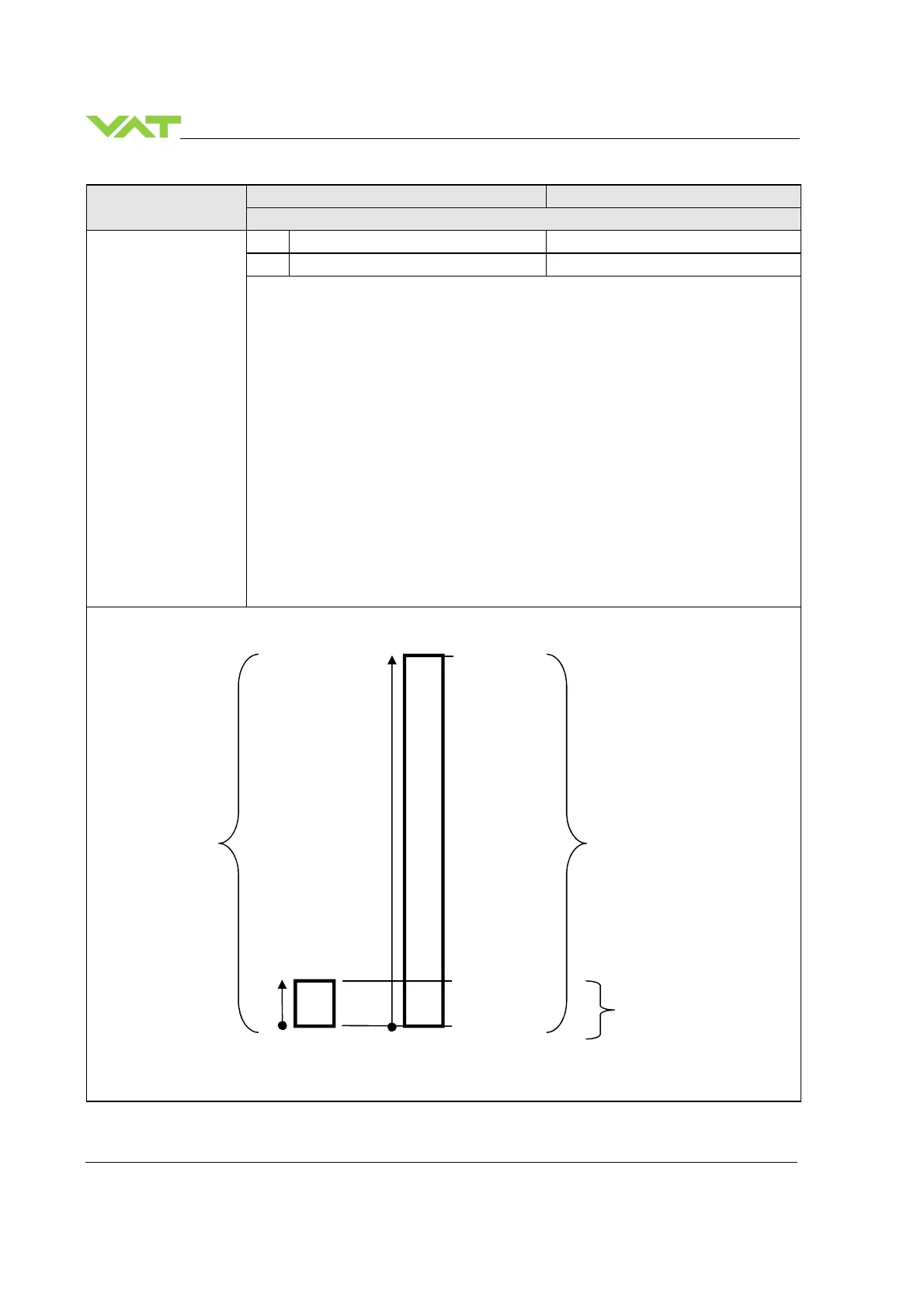
This function does the sensor configuration.
Above picture shows a 2 sensor system. In this configuration sensor 2 covers low range (100 mTorr) and sensor 1
covers high range (1 Torr). RANGE CONFIGURATION for PRESSURE resp. SENSOR READING is set to
1000’000. Switchover between sensors is done automatically.
sensor
sensor
0 – 1000’000
100 mTorr
0 mTorr
– 1000’000
0 – 1000’000
 Loading...


