Installation, Operating & Maintenance Instructions
Series 650, DN 100 – 250 (I.D. 4" - 10")
VAT Vakuumventile AG, CH-9469 Haag, Switzerland
Tel ++41 81 771 61 61 Fax ++41 81 771 48 30 Email reception@vat.ch www.vatvalve.com
258550EE
2007-05-11
14/51
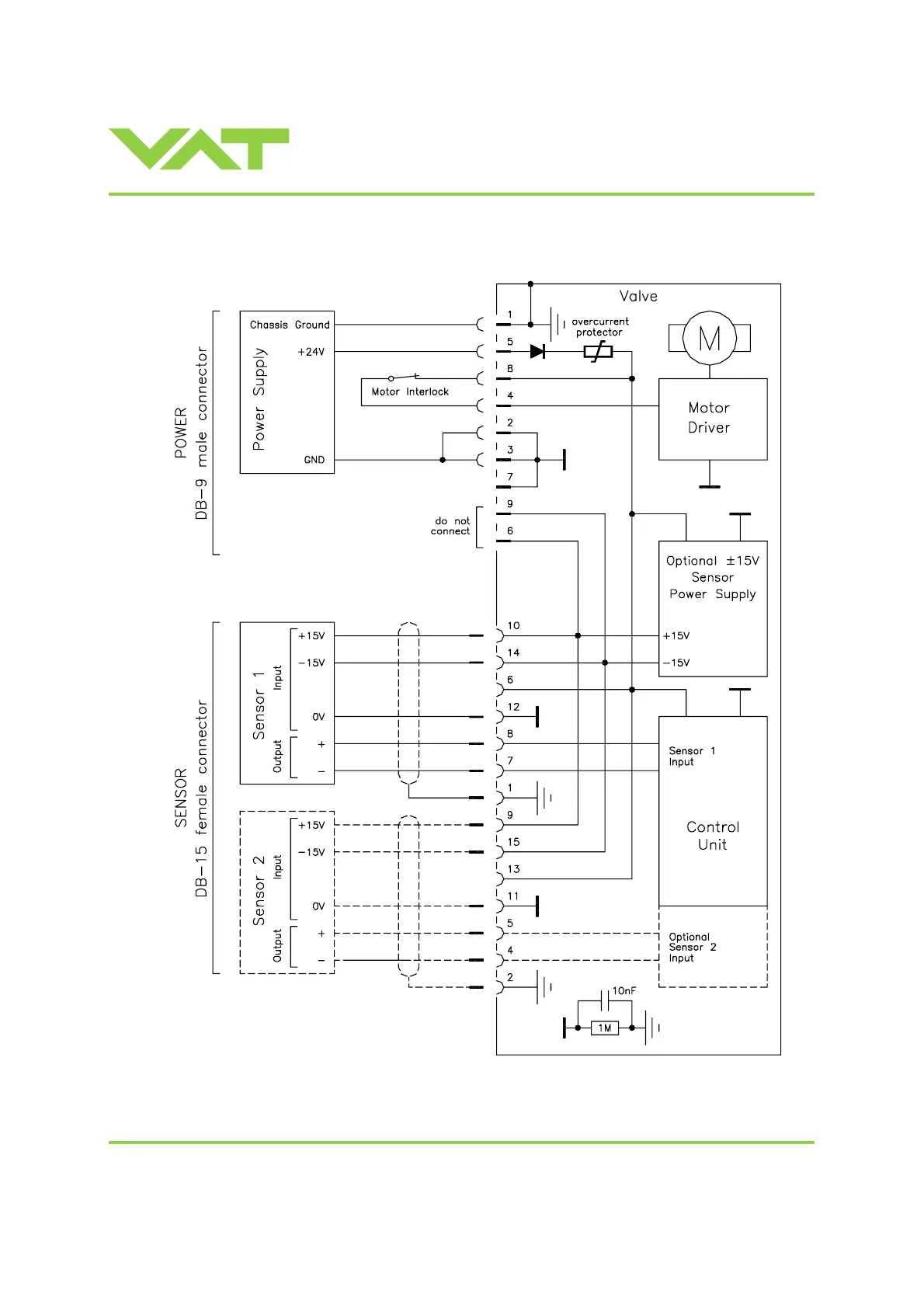
2.6.4 Power and sensor connection (±15 VDC sensors) with optional SPS module
[650 . . - . . A . - . . . . / 650 . . - . . C . - . . . . versions only]
Note: Use shielded sensor cable(s). Keep cable as short as possible, but locate it away from noise sources.
Pins 4 and 8 must be
bridged for operation!
An optional switch would allow
for motor interlock to prevent
valve from moving.
Low range sensor may be connected
to sensor 1 or sensor 2 input.
Do configuration accordingly.
 Loading...


