Installation, Operating & Maintenance Instructions
Series 650, DN 100 – 250 (I.D. 4" - 10")
VAT Vakuumventile AG, CH-9469 Haag, Switzerland
Tel ++41 81 771 61 61 Fax ++41 81 771 48 30 Email reception@vat.ch www.vatvalve.com
258550EE
2007-05-11
6/51
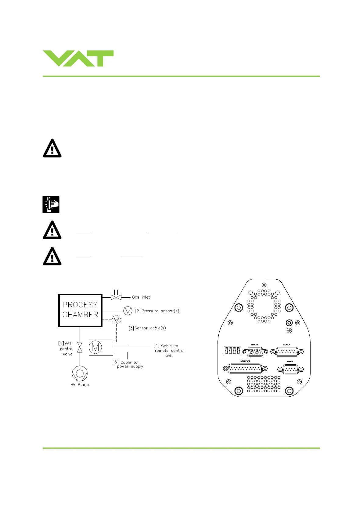
2 Installation
2.1 Unpacking
As this valve is a heavy component you should lift it with adequate equipment to prevent any injury to
humans.
DN200 (8”) and DN250 (10”) valves are equipped with attachment points (tapped holes). Add eyebolts
to these attachment points for lifting. The attachment points are indicated on the dimensional drawing of
the specific valve part number (available on request).
Never lay the valve down with control and actuating unit downwards as it may be damaged.
2.2 Installation into the system
Fingers and objects must be kept out of the valve opening and away from moving parts.
The valve plate may start to move just after power is supplied.
Do not
connect or disconnect sensor cable when device is under power.
Do not
disconnect air supply when device is under power.
 Loading...


