Installation, Operating & Maintenance Instructions
Series 650, DN 100 – 250 (I.D. 4" - 10")
VAT Vakuumventile AG, CH-9469 Haag, Switzerland
Tel ++41 81 771 61 61 Fax ++41 81 771 48 30 Email reception@vat.ch www.vatvalve.com
258550EE
2007-05-11
19/51
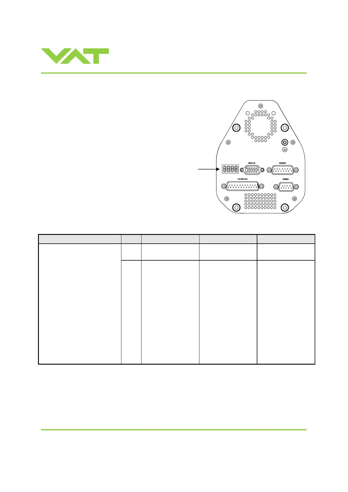
3.5 Display information
There is a 4 digit display located on the panel.
It displays configuration, status and position
information. For details see table on next
page.
Power up:
Description Digit 1
Digit 2 Digit 3 Digit 4
1 D 0 0
At first all dots are illuminated
then configuration is displayed:
• Firmware version [e.g. 1D00]
(1
st
information for about 2s)
• Controller configuration
(2
nd
information for about 2s)
SYNC indicates that power up
synchronization is running.
In case D C or D999 is displayed,
motor interlock is active. Refer to
«3.1.3 Safety mode» for details.
If valve is closed (isolated) display
shows alternately C C and INIT.
Syncronization will be done when
first movement command is
received.
1
= Logic
interface
0
= basic
1
= with SPS
1)
2
= with PFO
2)
3
= with SPS
1)
and PFO
2)
1
= 1 sensor version
2
= 2 sensor version
1) SPS = optional ±15 VDC Sensor Power Supply module 2) PFO = Power Failure Option
 Loading...


