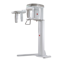
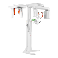
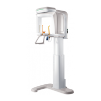
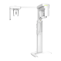
4. Imaging System Overview
Green Smart User Manual 23
ENGLISH
No. Item Description
8
Emergency Stop
Switch
Immediately stops the moving parts and cuts off all
power to the equipment’s electrical components.
9 Main Power Switch Turns on / off the main power of the equipment.
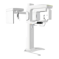
10
UP/DOWN Switch
(optional)
Adjusts the height of the Vertical Frame.
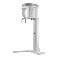
11 Stationary Column Supports the whole part of the equipment.
12 Base (Optional) Balances the equipment and maintains its safety.
13 LED Lamp
Displays the status of X-ray exposure.
- Green: Standby
- Yellow: In operation
14
X-ray Detector
for PANO / CBCT
Xmaru1404CF-Plus for PANO / CBCT imaging
sensor
15 Temple Supports
Supports the patient’s head by holding the temples.
Used in PANO and CBCT modes.
16 Chinrest The place to rest the chin.
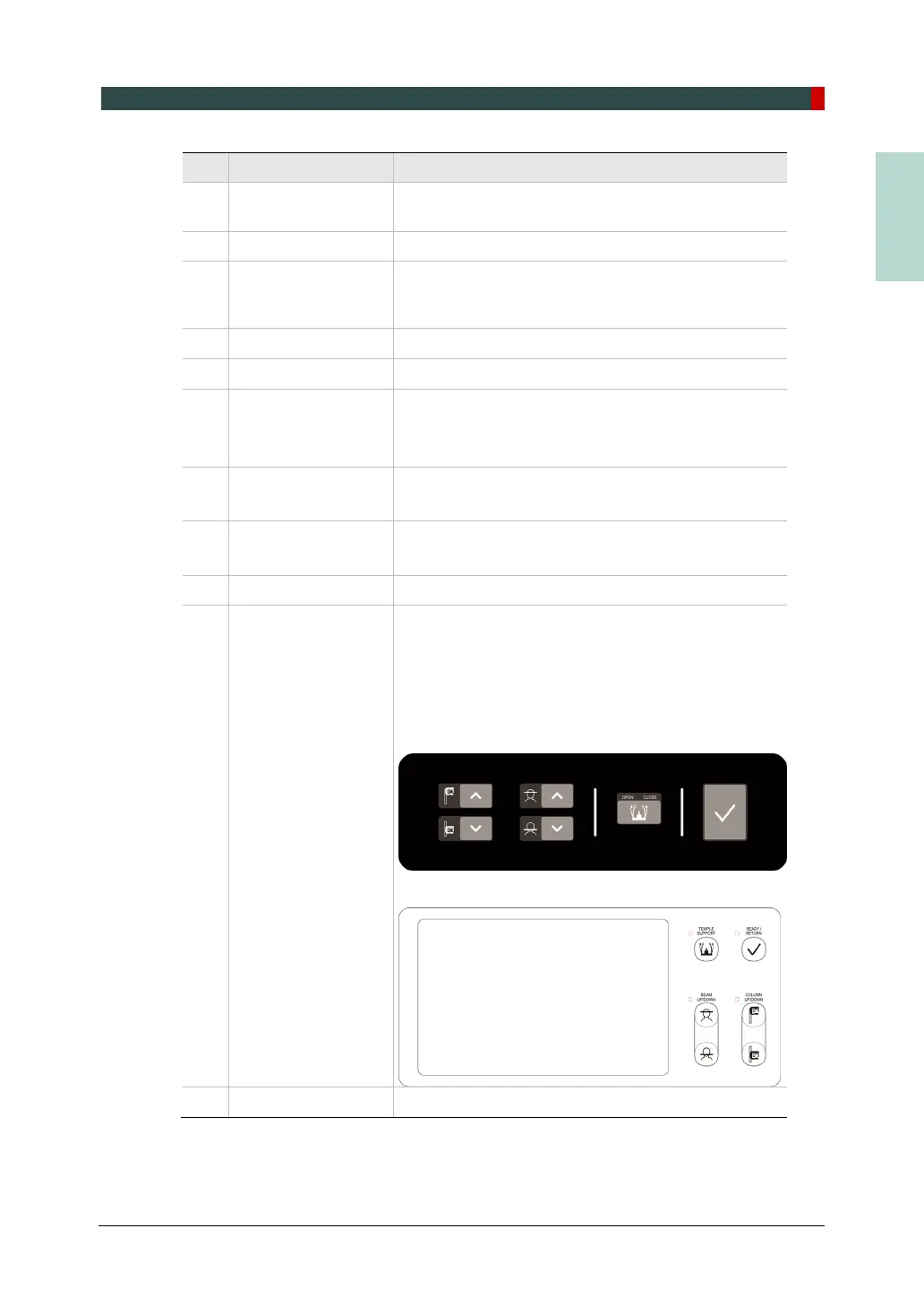
17 Control Panel
Operates the Horizontal Beam, opens/closes Temple
Supports, adjusts the height of the Vertical Frame
and prepares for operation when the READY button
is pressed. (For the details, refer to 4.6.1 Control
Panel.)
* The Membrane type control panel below is the
default.
* Control Panel with LCD screen is Optional.
18 D-Sub Connector The input signal port for Column UP/DOWN Switch