Do you have a question about the Vatech PaX-i Insight and is the answer not in the manual?
Manufacturer's liability for safe installation and operation under specific conditions.
Customer's responsibilities for site planning and preparation before system delivery.
Explanation of symbols used in the manual for warnings and important information.
Description and location of symbols used on the equipment and in the manual.
Requirements for the installation room, including visibility, floor type, and operator proximity.
Specifications for electrical installation, based on MEIGaN guidance notes.
Requirements for grounding, power lines, and voltage regulators for safe operation.
Environmental specifications for temperature, humidity, and pressure during operation and storage.
Describes three options for installing the exposure switch based on site configuration.
Guide to installing warning lamps and door interlock switches, referencing Appendix A.
Guide to installing the emergency stop switch, referencing Appendix B.
Lists the necessary tools required for the installation of the PaX-i Plus / Insight.
Instructions on checking ShockWatch and TiltWatch indicators on packages for damage.
Information on unpacking the main box, including component list and dimensions.
Introduction to checking the parts and accessories included in the package.
Procedure for unloading the main unit from its packaging onto the floor safely.
Instructions for assembling the base unit with the column unit using bolts.
Procedure for removing the transportation handle, specifically for units without the CEPH unit.
Steps to install the wall and column brackets securely onto the equipment.
Procedure for removing transportation safety bolts from the equipment.
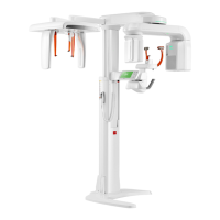
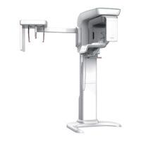
Step-by-step guide for installing the optional CEPH unit onto the main unit.
Instructions for fixing the base to a concrete floor using anchor bolts.
Guide for connecting optic cables and cable ties to the equipment's column.
Detailed steps for leveling the equipment using a spirit level and adjustment screws.
Procedure for aligning the optional CEPH unit using a spirit level and adjusting bolts.
Instructions for securely tightening all necessary bolts and bracket bolts.
General advice on planning and studying the installation environment for wall mounting.
Steps for leveling the equipment using a spirit level and adjusting set screws.
Instructions for securely tightening bracket bolts and floor anchor nuts.
Procedure for assembling the optional base cover using truss bolts.
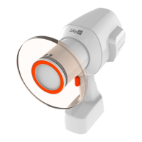
Instructions for inserting chinrest, bite block, temple supports, and cap ear rods.
Guide for installing switch holders for Up/Down switch and Exposure switch.
Diagram illustrating the direct connection of the equipment, PC, and optional accessories.
Specifies the minimum CPU, RAM, storage, and OS requirements for the PC.
Instructions for installing internal peripherals like the fiber optic frame grabber board.
Guide for connecting fiber optic cables and USB keys to the PC for data transfer.
Pre-setup checks for the emergency stop switch and program installation guidelines.
Procedure to disable the Windows Firewall to prevent interruptions in data transmission.
Steps to disable screen savers and set power options to 'Never' for uninterrupted operation.
Procedure to disable User Account Control (UAC) for smoother software operation.
Guide to excluding specific folders and files from anti-virus scans to prevent software conflicts.
Pre-installation checks for emergency stop switch, program compatibility, and virus scans.
Instructions for installing the image viewer program (EzDent-i or third-party) before the main package.
Step-by-step guide for installing the main software package using the InstallShield wizard.
Guide to setting up user information and running EzDent-i as an administrator.
Steps to configure imaging acquisition options within the EzDent-i software.
Guide to configuring parameters within the console software, including language and machine settings.
Procedure to disable the packing mode for proper equipment operation after installation.
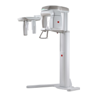
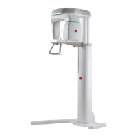
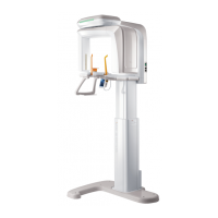
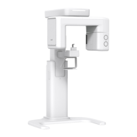
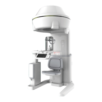
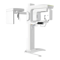
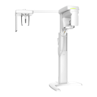
Detailed mechanical dimensions of the equipment with and without the CEPH unit and base.
Environmental operating and storage conditions for temperature, humidity, and pressure.
Information on reconstruction time for PaX-I Insight, dependent on computer specifications.
Requirements and block diagram for installing warning lamps and door interlock switches.
Guidelines for installing the emergency stop switch on the power cable line.
Procedure for limiting the column height within permissible range by measuring ceiling height.
Instructions for connecting a third-party exposure switch to the VATECH equipment.
Default PC BIOS settings for the HP Z440 model, including power options.
Checklist for general information about the equipment purchaser and seller.
| Radiation Dose | Low Dose |
|---|---|
| Generator Voltage (kVp) | 50 - 99 kVp |
| Type | Cone Beam CT |
| FOV (cm) | 5x5, 8x8 |
| FOV (mm) | 50x50, 80x80 |
| Detector Type | Flat Panel Detector |
| Voxel Size | 0.08 mm |
| Scan Time (Full) | 9 - 24 seconds (depending on FOV) |
| Software | EzDent-i |
| Generator Current (mA) | 4 - 10 mA |
| X-ray Generator | High Frequency |
| Dimensions | 1500mm (D) |
| Power Requirements | AC 220-240V |