Operating & Mounting instructions – 8 074 143.03/03 – Page 77
Connection
Power connections
For wiring the power and control terminals, the front cover must be removed. Do not apply mains
power to the motor terminals U, V, W, since this can cause damage to the frequency inverter.
In multimotor operation, a motor protection relay must be provided for each motor.
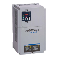
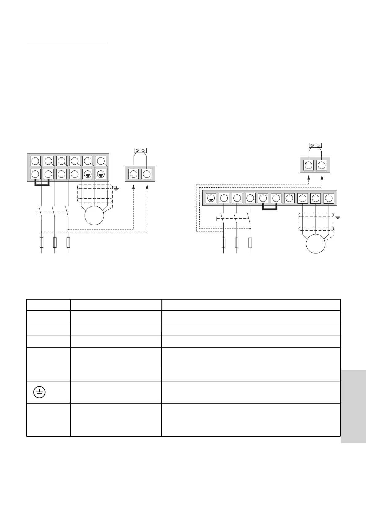
Power connections
>pDRIVE< CX profi 11 and 15 >pDRIVE< CX profi 18 to 37
1.) If an external voltage supply is used to maintain the supply for the electronics, the internal
connection between terminals R0, T0 and plug J51 must be removed
Terminal Function Description
L1, L2, L3 Mains connection 3 AC 380...480 V ±10%, 50/60Hz ±5 %
U, V, W Motor connection 0...mains voltage (typ.: 3 AC 400 V)
+, − Braking unit (Option) Connection for the braking unit
+, RB Braking resistor (Option) Connection for the braking resistor at internal braking
unit (only at CX profi 11 and 15)
+1, + Connection for DC choke Linked (factory default) !!
PE connection Min. 10 mm
2
or 2 wires electronically parallel via two
separated terminals.
R
0
, T
0
Supply of mains part Connection for the voltage supply of the mains part.
Can be used to maintain the control voltage at
switched-off power part (1 AC 400V).