Regulations
To satisfy the EMC directive 89/336/EEC, the following points should be kept:
1.) Mains voltage
• Voltage fluctuation ≤ ±10 %
• Voltage unbalance ≤ ±3 %
• Frequency variations ≤ ±5 %
• Voltage distortion (THD) ≤ 10 %
2.) Wiring
• For complying with the EMC-directive screened motor cables are required.
• For getting higher lengths of motor cable, it is necessary to connect an output motor filter
AMF to the output of the inverter, to reduce the stress of the inverter and the line filter caused
by the higher earth leakage currents.
• Seperate main circuit wiring from control circuit wiring.
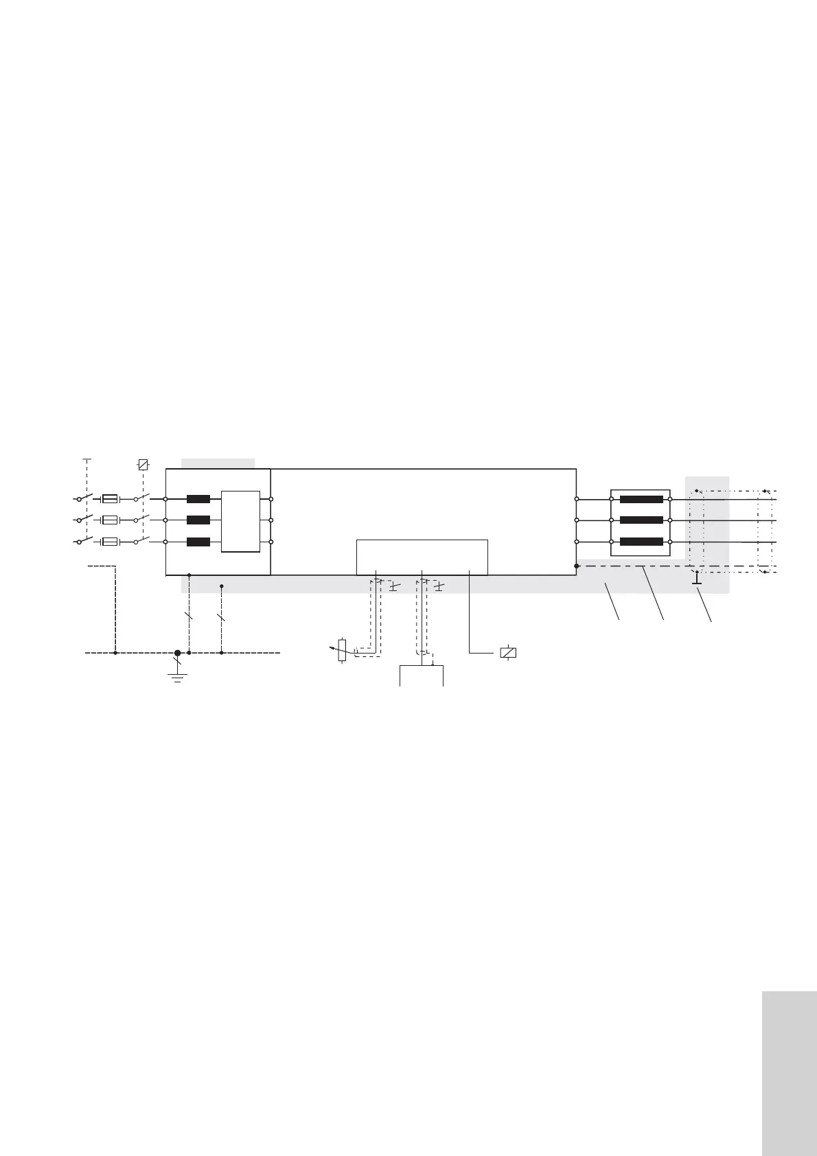
3.) Wiring diagram
HS ... Main switch
NH ... Mains fuses
NS ... Mains contactor
CE-Filter ... RFI-filter (with integraded line choke at CE-DR)
AMF ... Output-Motor-Filter
*) EMC earthing (earth connection on a large area to drain off the high-frequent
disturbances; maybe in parallel to the yellow/green wire) !!
**) Connect the screen on a large area on the mounting panel or directly on the CE-DR!!
***) Important: Well conductive mounting plate (i.e. precious steel or galvanized)
****) The PE conductor should be wired to the inverter as directly as possible, so that there is
good conduction of the interference signals to the filter, i.e. the PE terminal should be
insulated in the case of intermediate terminals.
ATTENTION:
Important for EMC corresponding installation of the drive is the good (HF) connection
of the motor cable to the CE-filter.