43
Eng
20,
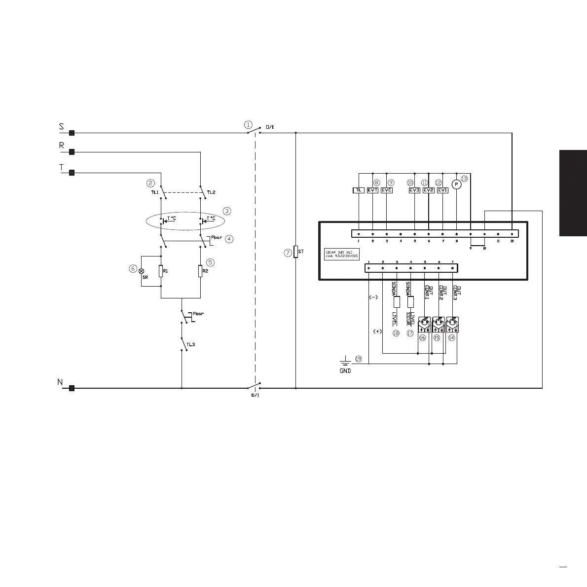
ELECTRICAL SCHEME.
LEGEND
1= Switch
2= Remote control switch
3= Safety thermostat
4= Pressure switch
5= Boiler heating element
6= Heating element LED
7= Cup heating plate
8= Tea solenoid valve
9= Filling solenoid valve
10= Unit 3 solenoid valve
11= Unit 2 solenoid valve
12= Unit 1 solenoid valve
13= Pump
14= 3-unit volumetric counter
15= 2-unit volumetric counter
16= 1-unit volumetric counter
17= Safety sensor
18= Level sensor
19= Frame ground
Manuale_LOLLO_Rev1_5lingue-Cinese_07-2016.indd 43 22/08/16 16:08