16
4 Mounting
FIBERTRAC 31 • Probus PA
43833-EN-170126
You can nd the exact number of Slaves in the Safety Manual.
L1L2
h
1
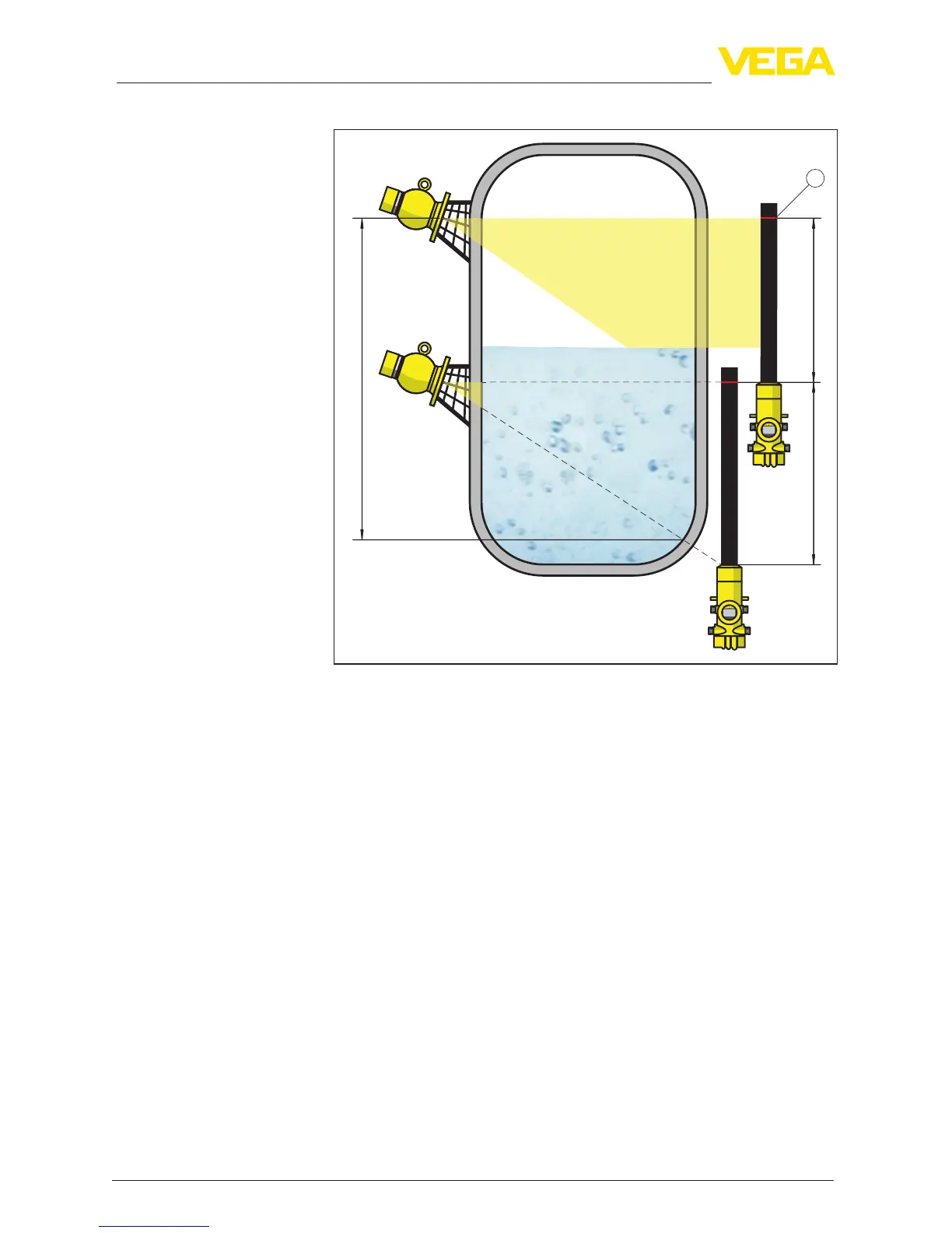
Fig. 5: Installation position - cascading arrangement
h Summed measuring range
L Measurement length (L1, L2)
1 Red marking line for designating the measuring range
Here, one instrument acts as a Master and all other instruments
operate as Summation Slaves. The pulse rates of all instruments
are summed in the Master instrument and converted into a common
signal.
If several sensors are cascaded, the measuring ranges of the indi-
vidual detectors must directly join each other. The detectors must also
slightly overlap.
Make sure that the red marking lines directly join the measuring range
of the next FIBERTRAC 31.
Mount the FIBERTRAC 31 in such a way that the detector hose
is directly in the radiated area of the source container. Mount the
FIBERTRAC 31 preferably side by side and make sure that no detec-
tor hose is hidden by another sensor.
On vessels with temperature insulation, the sensor and the source
container should be preferably mounted outside of the tank insulation.
Vessel with heat insula-
tion

 Loading...


