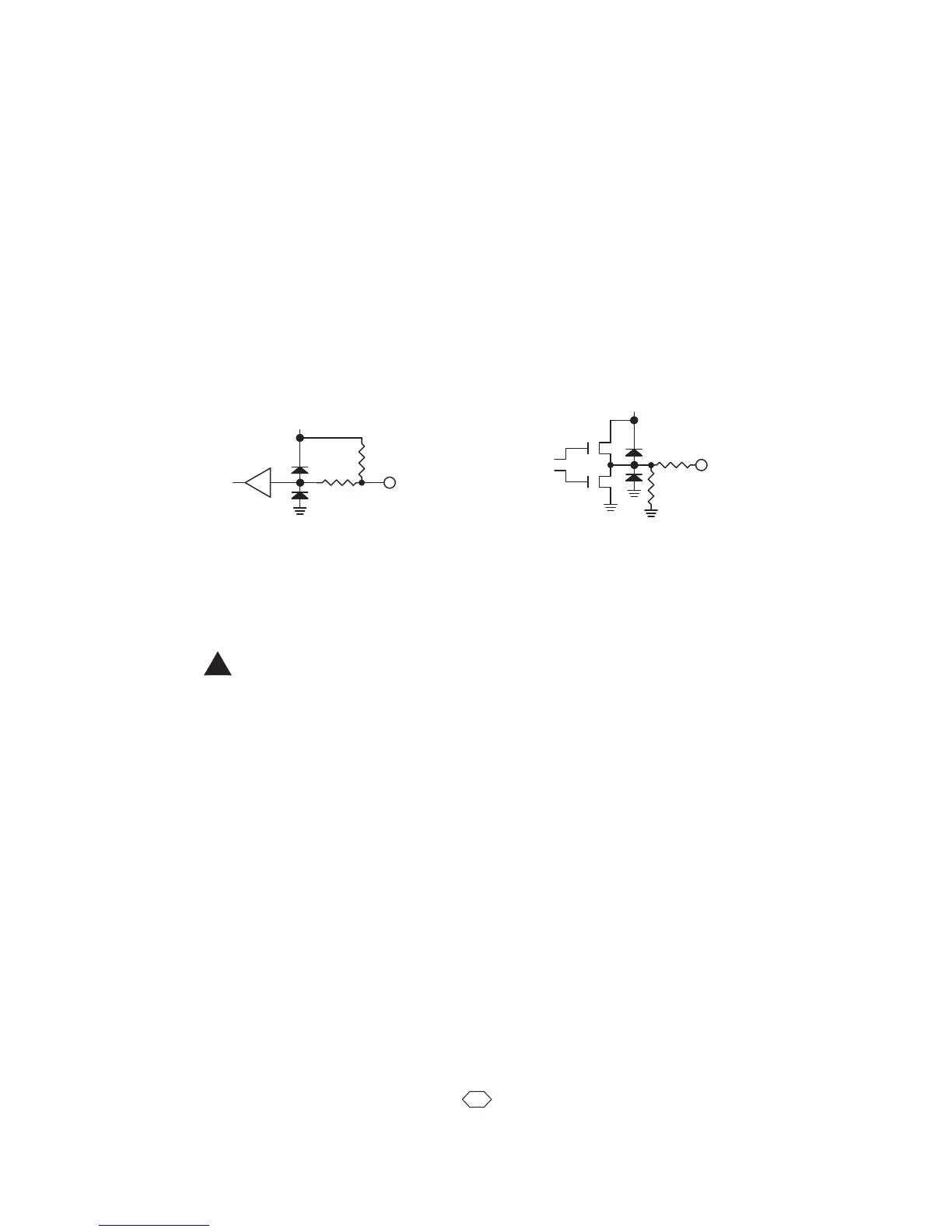
InputDiagram OutputDiagram
MCU
+5V
1K
2.2K
Input
MCU
+5V
P
N
100
10K
Output
Appendix K
I/O Electrical Specifications
AllUserI/Oinputsandoutputs(exceptlimitswitchinputs)areTTLlevels(0to+5VDC.)
Outputsarenormallylow,andcansinkandsource20mAmax.
Limitswitchinputsareopticallyisolated. Limitinputsoperateon24VDCthrougha10K
ohmresistortopowertheLEDintheopticalisolator(seeAppendixNformore
information.)
The+5VDConI/O,2isintendedforusewithadditionalanaloginputcircuitry. Current
drawshouldnotexceed75mA.
NeverdirectlyconnectaVXMI/Otoaninductiveload,anydevicethatisnotwithin10feet
oftheVXM,oranythingnotpoweredatthesameACsource.
DamageduetoimproperlyinterfacingVXMcontrollerstootherdevicesisnotcovered
underthewarranty.
Asaminimumprecautionagainstelectrostaticdischarge(ESD)damagefollowthese
guidelines:
1.
Providetheshortestconductivepathpossibletoearthgroundfromuser
designedpanelsorenclosuresthathaveswitchesorbuttonstheoperatorwill
comeincontactwith.
2.
Usemetalpanelsandenclosurestohousebuttonsorswitcheselectrically
bondedtoaprotectiveearthground.
3.
UseshieldedcablesonallVXMI/O.
4.
Ifnootherprotectiveearthgroundisavailable,usetheearthgroundonthe
VXMsAuxiliaryI/Oconnectorshellorconnectorshellonshieldedcable.
Inputshavea2200ohmresistorto+5VDC,andareactivatedbyconnectingto0V.
NOTE: When Input 4 (Stop) is held low (0V) program will not run.*
Optically isolated relays may be required on all user I/Os to insure long term
reliable operation.
CAUTION:
* New feature: Only on VXM firmware versions 1.21 & up
!