- 3-
Safety Considerations
Hazards may exist within this equipment because it
contains electrical and powerful moving components.
Only qualified service personnel should install or service
this equipment. Untrained personnel can perform basic
maintenance such as maintaining filters. Observe pre-
cautions marked in literature and on labels attached to
the unit. Follow all safety codes.
General Information
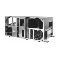
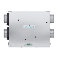
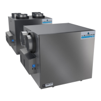
Energy Recovery Ventilators (ERVs):
ERV500i and ERV500e
The ERV500i ventilator is intended for installation with-
in a suspended ceiling space or mechanical room. The
ERV500e ventilator is intended for installation on a
rooftop with a factory supplied or field supplied roofcurb.
These ventilators provide 100% outdoor air ventilation
and provide energy recovery between the exhaust and
supply airstreams. The Energy Recovery Ventilators
(ERVs) use an enthalpy wheel for total energy recovery
which provides superior efficiency in hot and humid cli-
mates. In addition, they provide excellent heat recovery in
winter and transfer moisture from exhausted air to the
outdoor air before supplying it to an occupied space.
Installation
Check Equipment
Move the unit to its installation location and remove pack-
aging. See Appendix F for unit weight and specifications.
Inspect the exterior and interior of the equipment for
damage. Ensure there is no damage to internal compo-
nents such as fans, motors, dampers, enthalpy wheel,
insulation, etc. File a claim with the shipping company if
the unit is damaged.
System Requirements
Consult local building codes and the National Electrical
Code for special installation requirements. Note additional
requirements below and in the Start Up Section.
Mount Unit
Interior Mount
The unit should be installed to allow easy access for
maintenance. Appendix B shows minimum clearance
required between front access and any obstruction to
allow for removal of components (fans, filters, enthalpy
wheel). The front of the unit is defined in relation to the
inlet ports and outlet ports on the unit. Port location and
overall dimensions are shown in Appendix B. Unit com-
ponents are shown in Appendix E.
In cold climates (-5°F [-20°C] design), the unit must be
mounted in a dry area (not exceeding 30% RH) to avoid
condensation on the exterior of the cabinet during winter
operation. Alternatively, accommodation must be made
for condensation on the cabinet exterior. Do not mount
units in an area where exposure to hot chimneys, electri-
cal panels or other hazards will occur.
A mounting location close to an exterior partition will
minimize the length of insulated ductwork required.
Exhaust air to outside and inside air ducts must be insu-
lated. Inlet and exhaust hoods should be separated by
a minimum of 10 feet [3048mm] to avoid outside cross
contamination.
Ceiling Mount
The unit must be mounted level and may be hung with
threaded rod (field supplied) through the protruding frame
at the base of the unit. Hole centers are shown in the
overall dimensional drawings in Appendix B. Rubber or
seismic vibration isolation may be required in some
regions (field supplied and specified).
Surface Mount
The unit may be secured to a metal or wooden curb fas-
tened to the floor. If securing the unit to the curb is
required, fasteners and isolators may be used at the
mounting points on the frame protruding from the unit (all
mounting hardware is field supplied and specified).
Rooftop Mount
(ERV500e ONLY)
Care must be exercised in locating the roofcurb for the
unit on the roof opening. The HVAC system should cross
enough roof supports to safely distribute the weight of the
system over the roof. For hole sizes of the units, see
Appendix B. For more roofcurb information, see Appendix A.
Remove roofcurb from packaging. Assemble and install
accessory roofcurb in accordance with instructions shipped
with the curb. See Appendix A for curb dimensions. Install
cant strip, flashing and roof felt as per Appendix A.
Ductwork must be attached to the roofcurb, not the unit.
Consult with local authorities or your local building code
for minimal intake hood height from the roof to determine
the height of the roofcurb. See Appendix B for dimensions
of the unit.
WARNING
Disconnect the main power switches to the unit before
performing service or maintenance. Electric shock can
cause personal injury.
IMPORTANT
The gasketing of the unit to the roofcurb is critical for a
watertight seal. Install gasket with the roofcurb as
shown in Appendix A. Improperly applied gasket can
result in water leaks and poor unit performance.